
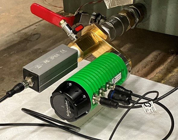
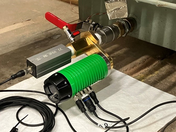
Installing the EcoStruxure Transformer Expert Sensor H2
Install the ETE H2 and ETS to an oil-filled transformer.
 DANGER DANGER |
|---|
|
HAZARD OF ELECTRIC SHOCK, EXPLOSION,
OR ARC FLASH
Only mount or unmount the sensor when the transformer
is de-energized.
Failure to follow these instructions will result in death or serious injury.
|
| NOTICE |
|---|
|
hazard of UNINTENDED EQUIPMENT OPERATION
Do not install the sensor with more than 30 mm (1.18 inch)
of the sensor tip extending into the transformer tank.
Failure to follow these instructions can result in equipment damage.
|
-
The ETE adapter with oil sample valve is referred as “the adapter valve”.
-
The transformer valve is referred as “the valve”.
-
Clean the valve, make sure it is closed, and position.
-
Place the drip collector under the valve connector to avoid any oil spillage on the ground when removing the cap or blank flange of the valve.
-
Firmly close the oil valve.
-
Remove the cap or blank flange, and check there is no oil leak along the threads.
-
Clean the valve orifice, valve flange, and threads.
-
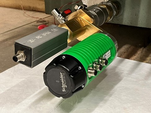
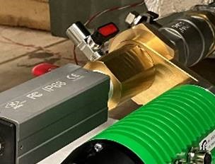
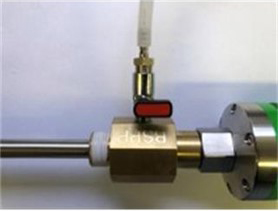
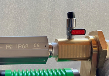
Assemble the body of the adapter with the ETE support and its locking nut, as shown.
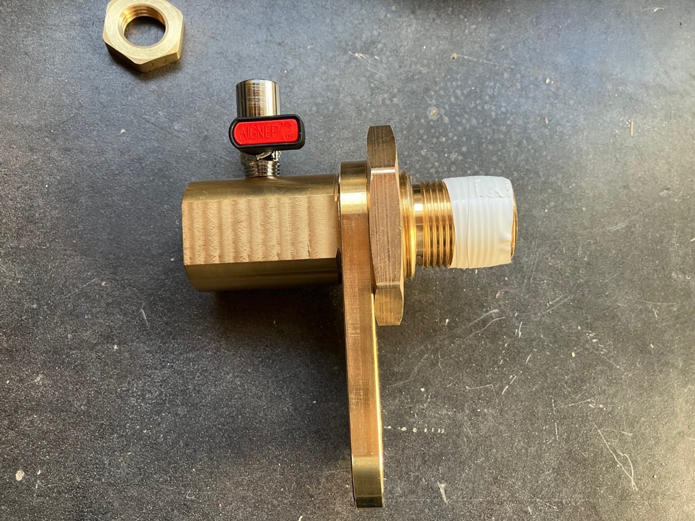
Block the support and the nut to set the ETE support in the opposite way to the drain valve. Set the PTFE tape on the plug thread.
-
In the case of NPT thread socket on the valve, use PTFE tape to screw the 1 inch NPT/BSPP adapter into the valve's socket thread (if you have a BSPP thread socket, skip this operation and proceed to Step 8).
-
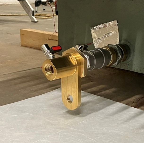
Using PTFE tape, screw the ETE adapter (1 inch BSPP plug) into the socket thread on the oil valve or onto the NPT/BSPP adapter that you assembled in the previous step.
-
After tightening, check that the bleeder valve or oil sample valve in the adapter faces upwards. As the adapter, ETE logger and the sensor H2 is heavy, the length of the thread plug shall be engaged by a minimum of 15 mm into the socket.
-
Make a note of the seven-digit logger ID, to check the status of the probesensor through the website.
NOTE: After mounting on the transformer, you cannot read the ID. -
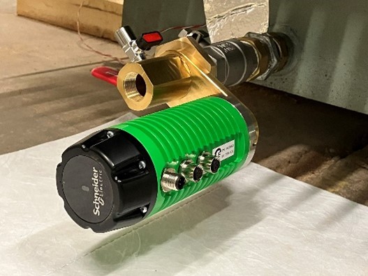
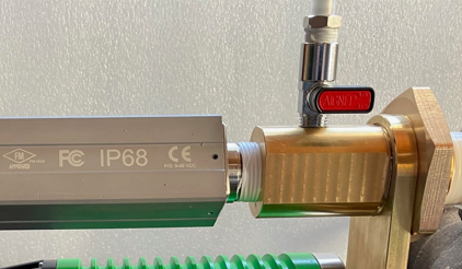
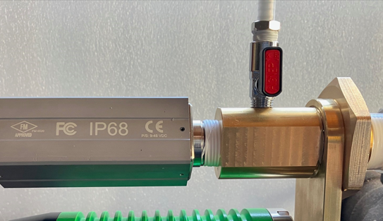
Screw ETE logger and check the M12 connection port are facing downward and fasten it with the ETE locking nut.
-
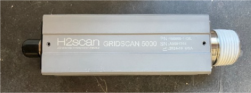
Using PTFE tape, screw the Gridscan sensor (plug 3/4 inch NPT) into the socket thread on the valve adapter, and tighten it firmly.
-
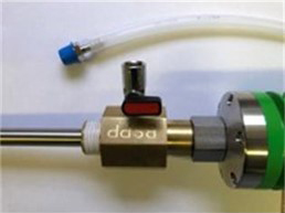
Bleed the air:
-
Make sure that the valve is closed.
-
Remove the plug and keep it aside.
-
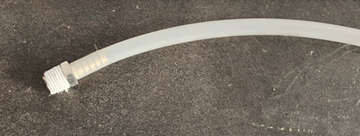
Remove the cap from the barb and wrap the plug thread with PTFE tape.
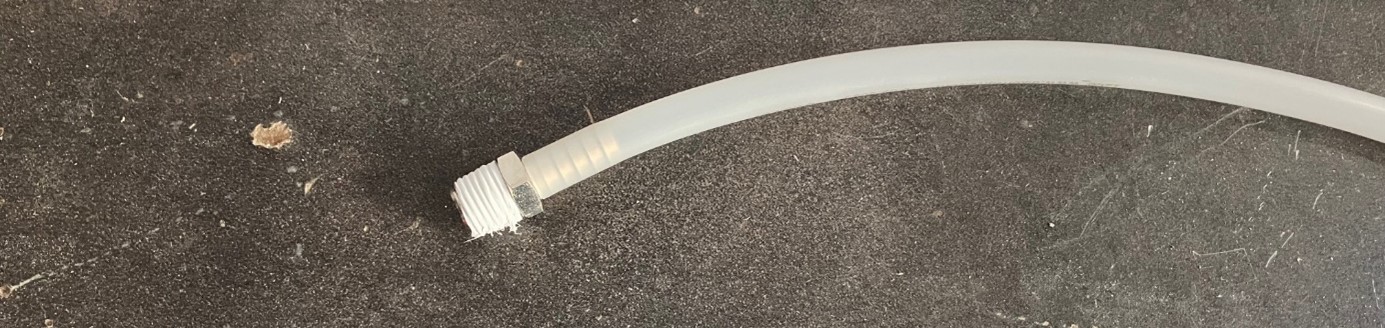
-
Insert the barb fully into the tube for a secure fitment.
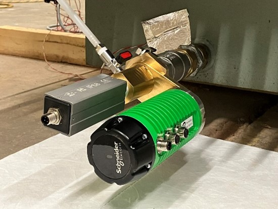
-
Turn the adapter valve to the open position.
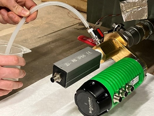
-
Open the transformer oil valve.
IMPORTANT: For a ball or butterfly valve, open the valve slowly.NOTE: Opening the valve too fast may induce a water hammer effect creating an extra force on the tube. -
When oil starts to come out, it means that air has been successfully removed. Turn the valve to the closed position.
-
Remove the barb and attach the plug cap to the valve.
-
-
Connect all cables and tighten ETE logger facing downward.
-
Connect the H2 cable (Modbus cable with M12 connector on both side).
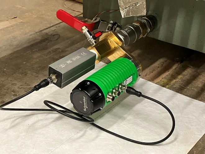
-
Plug the ETS cable (M12 port 8 pins) and route it the selected place (see “Mounting the ETE Sensor and External Temperature sensor (ETS)”) enabling to measure the opposite temperature complementary to the temperature measured by the sensor H2.
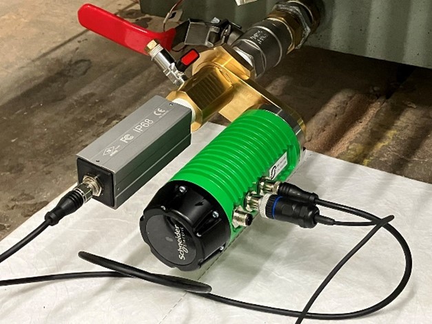
-
Plug the power cable (M12 port 4 pin) and route it to the marshalling box where the AC/DC converter is installed.
-
Turn ETE logger to have the cables facing downward and tighten the ETE logger nut firmly.
-
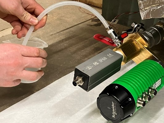
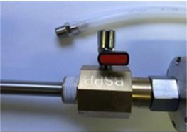
Oil Sampling Process
-
Make sure that the valve is closed.
-
Remove the plug and keep it aside.
-
Remove the cap off the barb.
-
Connect the barb and make sure that the sampling tube is fitted tightly on the barb.
-
Install the sampling vessel below the open end of the sampling tube.
-
Turn the valve to the open position until the necessary oil sample has been collected.
NOTE: Clean the tube before you take the sample. Let 10 cl of oil flow to remove any contaminants.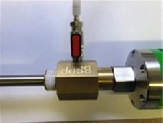
-
Turn the valve to the closed position.
-
Remove the barb and the sampling tube.
-
Wipe down the items.
-
Install the plug back to the adapter.
Oil Sampling Process
-
Make sure that the valve is closed.
-
Remove the plug and keep it aside.
-
Remove the cap off the barb.
-
Connect the barb and make sure that the sampling tube is fitted tightly on the barb.
-
Install the sampling vessel below the open end of the sampling tube.
-
Turn the valve to the open position until the necessary oil sample has been collected.
 NOTE: Clean the tube before you take the sample. Let 10 cl of oil flow to remove any contaminants.
 -
When sampling is done, turn the valve to the closed position.
-
Remove the barb and the sampling tube.
-
Wipe down the items.
-
Install the plug back to the adapter.
Finishing Tasks
Complete the ETE Sensor installation by following these steps:
-
Empty the contents of the drip tray into a special storage container.
-
Place all oil contaminated waste material in a bag for disposal in accordance with local regulations.
-
On completion, clear all tools and materials and cancel any work permits issued by the operator.
Fitting the ETE Sensor and External Temperature Sensor
Specific recommendations:
-
Install the ETE Sensor in a location where the tip of the probe measures the top oil temperature.
Install the ETE External Temperature Sensor to measure the top oil temperature.
-
For transformers equipped with radiators, this is on the top of the tank, and for transformers with corrugated wall tanks, this is on the cover.
-
When the transformer is designed with a gas cushion, the probe fitting is designed to improve the immersion of the probe tip in the oil flow.
-
The dedicated fitting for the ETE Sensor is composed of:
-
Inside a control cabinet, an additional MCB 2A (not supplied) is installed for the AC/DC converter, and a dedicated space is provided to fix the
AC/DC converter. A dedicated cable gland (power cable of the ETE Sensor diameter of 4.8 mm (0.19 inch) is fitted on the cable gland plate. -
The external temperature sensor is fixed to the bottom pipe of a radiator (or other type of cooling system). In the case of a corrugated wall, fix it on a short piece of tube (DN 50) welded as near as possible to the bottom of the fins
-
A mechanical and thermal protection of the external temperature sensor is needed.
-
Cable trays or cable supports are also needed to route the power supply cable and the cable for the external temperature sensor.
NOTICE Hazard of UNINTENDED EQUIPMENT OPERATIONCable trays or supports must respect the minimum dielectric distance to the live parts according to the voltage level of the transformer (refer to the IEC 60076 standard).Failure to follow these instructions can result in equipment damage.
-
Mounting the ETE Sensor and External Temperature Sensor (ETS)
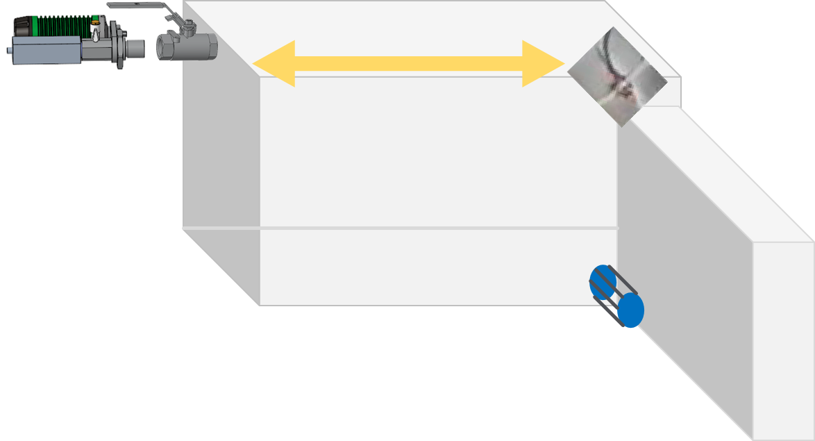
The ETE sensor can be installed in either the top oil valve (preferred) or the bottom oil valve. The ETE algorithms require top oil temperature from ETS. The ETS must be installed always at the top.
Ideal mounting
 |
 |
 |
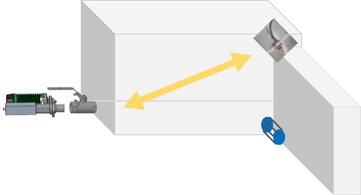 |
Mounting the ETE Sensor and External Temperature Sensor (ETS)
The ETE sensor can be installed in either the top oil valve (preferred) or the bottom oil valve. The ETE algorithms require top oil temperature from ETS. The ETS must be installed always at the top.
Ideal mounting
|
|
|
|