Dimensioning
Cross-Sectional Area of Protective Conductors
Reproduced Articles from IEC 60364-5-54
543 Protective Conductors
543.1 Minimum cross-sectional areas
543.1.1 The cross-sectional area of every protective conductor shall satisfy the conditions for automatic disconnection of supply required in clause 413.1 of IEC 60364-4-41 and be capable of withstanding the prospective fault current.
The cross-sectional area of the protective conductor shall either be calculated in accordance with 543.1.2, or selected in accordance with table 54.3. In either case, the requirements of 543.1.3 shall be taken into account.
Terminals for protective conductors shall be capable of accepting conductors of dimensions required by this subclause
543.1.2. The cross-sectional areas of protective conductors shall not be less than the value determined either
-
in accordance with IEC 60949;
-
or by the following formula applicable only for disconnection times not exceeding 5 s:

where
| S | is the cross-sectional area, in mm2 |
| I | is the value (r.m.s) in A of prospective fault current for a fault negligible impedance, which can flow through the protective device (see IEC 60909-0); |
| t | is the operating time of the prospective device for automatic
disconnection in s; Note 1: Account should be taken of the current-limiting effect of the circuit impedances and the limitation of I2t of the protective device. |
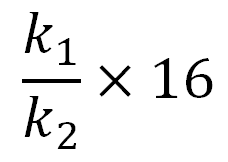
| k | is the factor dependent on the material of the protective conductor, the insulation and other parts and the initial and the final temperatures (for calculation of k, see annex A). |
If application of the formula produces non-standard sizes, conductors of a higher standard cross-sectional area shall be used.
Note 2: For limitations of temperatures for installations in potentially explosive atmospheres, see IEC 60079-0.
Note 3: As the metallic sheaths of mineral insulated cables according to IEC 60702-1 have an earth fault capacity greater than that of the line conductors, it is not necessary to calculate the cross-sectional area of the metallic sheaths when used as protective conductors.
543.1.3 The cross-sectional area of every protective conductor which does not form part of the cable or which is not in a common enclosure with the line conductor shall be not less than
-
2,5 mm2 Cu/16 mm2 Al of protection against mechanical damage is provided
-
4 mm2 Cu/16 mm2 Al of protection against mechanical damage is not provided
Values of k for Phase Conductor
| Conductor isolation | ||||||
| PVC ≤300 mm2 | PVC >300 mm2 | EPR XLPE | Rubber 60 °C | Mineral | ||
| PVC | Bare | |||||
| Initial temperature °C | 70 | 70 | 90 | 60 | 70 | 105 |
| Final temperature °C | 160 | 140 | 250 | 200 | 160 | 250 |
| Material of conductor: Copper Aluminum Tin-soldered joints in copper conductors |
115 76 115 |
103 68 – |
143 94 – |
141 93 – |
115 – – |
135/115* – – |
Note 1: Other values of k are under consideration
for:
Note 2: The nominal current of the short-circuit protective device may be greater than the current-carrying capacity of the cable. Note 3: The above factors are based on IEC 60724. |
||||||


