
Parameter Descriptions
1. Configuration
The parameters in Configuration define basic aspects of the user application and how the soft starter will interact with the motor.
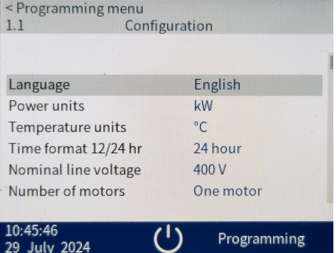
1.1 Language
Selects which language the keypad will use to display messages and feedback.
| Options: | |
|---|---|
|
English |
(default) |
|
中文 |
Simplified Chinese |
|
Español |
Spanish |
|
Italiano |
Italian |
|
Français |
French |
|
Deutsch |
German |
|
Português |
Brazilian Portuguese |
1.2 Power Units
Selects whether the starter will display power in kilowatts or horsepower. The data in the log viewer will also be displayed in the selected units. This parameter is set in the factory.
| Options: | |
|---|---|
|
kW |
|
|
hp |
|
|
Factory reset |
(default) |
1.3 Temperature Units
Selects whether the starter will display temperatures in degrees Celsius or Fahrenheit. This parameter is set in the factory.
| Options: | |
|---|---|
|
°C |
|
|
°F |
|
|
Factory reset |
(default) |
1.4 Time Format 12/24 Hour
Selects whether the time will be shown in 12- or 24-hour format on the home screen. This parameter is set in the factory.
| Options: | |
|---|---|
|
12-hour |
|
|
24-hour |
|
|
Factory reset |
(default) |
1.5 Nominal Line Voltage
Sets the reference voltage. This affects voltage ramp and power ramp starting and stopping, as well as undervoltage/overvoltage protection. This parameter is set in the factory.
| Range: | |
|---|---|
|
0–15000 V |
0 V (default) |
1.6 Number of Motors
Selects whether the starter is connected to one or two motors. If connected to two separate motors, the starter will use separate thermal models. This parameter is set in the factory.
| Options: | |
|---|---|
|
One motor |
|
|
Two motors |
|
|
Factory reset |
(default) |
1.7 Active Start/Stop Sets
Selects whether the starter will use one or two sets of start/stop parameters. Two start/stop parameter sets can be used for two separate motors, or for a single motor that may start in two different conditions (such as a conveyor that may start loaded or unloaded). This parameter is set in the factory.
| Options: | |
|---|---|
|
One set |
|
|
Two sets |
|
|
Factory reset |
(default) |
1.8 Motor Connection
Selects whether the soft starter is connected to the motor in-line or inside delta. This parameter is set in the factory.
| Options: | |
|---|---|
|
In-line/3-wire |
|
|
Inside delta/6-wire |
|
|
Factory reset |
(default) |
1.9 PIN Access Policy
Sets the access policy for the starter. You can select which portions of the menus will be locked. The customer sets this parameter.
|
Options: |
|
|---|---|
|
No PIN required |
No PIN required. Users can access all menus. |
| Tools locked |
Select this option to lock the Tools menu. The user will need to enter a PIN to access this menu. |
|
Params and Tools locked |
Select this option to lock the Programming menu and Tools submenu. The user will need to enter a PIN to edit the parameters and access the Tools menu. |
|
Customer set |
This is the default setting. The user must select another option when a new unit is powered up for the first time. |
2. Motor 1 Settings
Configure the starter to match the connected motor. These parameters describe the motor's operating characteristics and allow the starter to model the motor's thermal overload content.

2.1 Rated Full Load Amps
Matches the starter to the connected motor's full load current. Set to the full load current (FLA) rating shown on the motor nameplate.
|
Range: |
|
|---|---|
|
4500 A |
10 A (default) |
2.2 Service Factor
Sets the motor service factor used by the thermal model. If the motor current is above Service Factor FLA, the overload content will increase and reach 100%, thus tripping the starter. If the motor current is below Service Factor FLA, it will decrease and reach a value below 100% (steady state).
-
For NEMA motors, set this parameter according to the motor nameplate.
-
For IEC motors, set this parameter to 1.0.
For more information, see Motor Overload Protection and Motor Service Factor.
|
Range: |
|
|---|---|
|
1.00–1.25% |
1.05% (default) |
2.3 Rated Power
Sets the running power of the connected motor, in kilowatts. The equivalent horsepower is also displayed. This setting is the basis for power reporting and protection. It is also used by TruTorque.
|
Range: |
|
|---|---|
|
0–65000 kW/87131 hp |
100 kW (default) |
2.4 Rated Power Factor
Sets the power factor of the connected motor.
|
Range: |
|
|---|---|
|
1–100 pf |
85 pf (default) |
2.5 Machine 1 Name
Assigns a name to the motor. The machine name is displayed in the top left corner of the display.
The name can be configured at any time. Use the app to edit the name. See Set Custom Display Messages for details.
| Options: | |
|---|---|
|
Motor 1 |
(default) |
| Custom Name/Message | |
2.6 Overload Trip Class
Determines how quickly the starter will trip in the event of an overload condition. The motor can run at 600% of the programmed FLA for the time selected, before tripping on 'Motor overload'. For details, see Motor Overload Protection.
| Range: | |
|---|---|
|
2–70 |
10 (default) |
2.7 Hot/Cold Ratio
Sets the level that the thermal overload content will reach when the motor is running in normal conditions. This allows accurate motor overload protection during a warm start.
|
Range: |
|
|---|---|
|
0–99% |
60% (default) |
2.8 Overload Cooling Time
Sets how long it takes for the motor thermal overload content to cool from 100% to less than 1%, while the motor is stopped.
|
Range: |
|
|---|---|
|
00:01–3:00 (hh:mm) |
00:30 hh:mm (default) |
2.9 Overload Lockout
The thermal overload content must be below the overload lockout for the starter to allow a start.
If an overload lockout occurs, the screen will display the overload level and the expected time to cool to the lockout level.
|
Range: |
|
|---|---|
|
1–99% |
15% (default) |
2.10 Motor Overload Lockout Calculation
If this parameter is set to automatic, the overload lockout is calculated using the last four starts instead of from the parameter.
It will automatically calculate the overload content required to start the motor. It will lockout the starter if there is not enough overload content available. The release value calculated is based on the average overload content used for the past four (4) successful motor starts. A factor of 1.25 is applied as an application margin.
For example:
The overload content used for the past 4 starts were 30%, 29%, 30%, 27%.
step 1 (30+29+30+27) / 4 = 29%
step 2 29% * 1.25 = 36%.
step 3 100% - 36% = 64% Therefore 64% is the calculated overload lockout.
| Options: | |
|---|---|
|
Automatic |
|
| Off | (default) |
2.11 Maximum Starts/Hour
Sets the maximum number of starts the starter will allow in a 60 minute period.
After the final allowable start, the display shows the time remaining before another start can be attempted. See also Starter ‘Waiting’ States.
|
Range: |
|
|---|---|
|
1–30 |
10 (default) |
2.12 Minimum Time Between Starts
The starter can force a delay between starts. The delay applies regardless of running time or stopping time. During the restart delay period, the display shows the time remaining before another start can be attempted.
| Range: | |
|---|---|
|
00:00–03:00 (hh:mm) |
00:00 hh:mm (default) |
3. Motor 2 Settings
Configure the soft starter to match the connected motor. These parameters describe the motor's operating characteristics and allow the soft starter to model the motor's thermal overload content. The Motor 2 Settings are only available if the number of motors is set to two motors.

3.1 Rated Full Load Amps
Sets the secondary motor's full load current.
3.1 Rated Full Load Amps
|
Range: |
|
|---|---|
|
4500 A |
10 A (default) |
3.2 Service Factor
Sets the motor service factor used by the thermal model. If the motor current is above Service Factor * FLA the overload content will increase and reach 100%, thus tripping the starter. If the motor current is below Service Factor * FLA, it will decrease and reach a value below 100% (steady state).
-
For NEMA motors, set this parameter according to the motor nameplate.
-
For IEC motors, set this parameter to 1.0.
For more information, see Motor Overload Protection and Motor Service Factor.
|
Range: |
|
|---|---|
|
1.00–1.25% |
1.05% (default) |
3.3 Rated Power
Sets the running power of the connected motor in kilowatts. The equivalent horsepower is also displayed. This setting is the basis for power reporting and protection. It is also used by TruTorque.
|
Range |
|
|---|---|
|
0–65000 kW/87131 hp |
100 kW (default) |
3.4 Rated Power Factor
Sets the power factor of the connected motor.
|
Range: |
|
|---|---|
|
1–100 pf |
85 pf (default) |
3.5 Machine 2 Name
Assigns a name to the motor. The machine name is displayed in the top left corner of the display.
The name can be configured at any time. Use the app to edit the name. See Set Custom Display Messages.
|
Options: |
|
|---|---|
| Motor 2 | (default) |
| Custom Name/Message | |
3.6 Overload Trip Class
Determines how quickly the starter will trip in the event of overload condition. The motor can run at 600% of the programmed FLA for the time selected, before tripping on 'Motor overload'. For details, see Motor Overload Protection.
|
Range: |
|
|---|---|
|
2–70 |
10 (default) |
3.7 Hot/Cold Ratio
Sets the level that the thermal overload content will reach when the motor is running in normal conditions. This allows accurate motor overload protection during a warm start.
|
Range: |
|
|---|---|
|
0–99% |
60% (default) |
3.8 Overload Cooling Time
Sets how long it takes for the motor thermal overload content to cool from 100% to less than 1% of the thermal model, while the motor is stopped.
|
Range: |
|
|---|---|
|
00:01–3:00 (hh:mm) |
00:30 hh:mm (default) |
3.9 Overload Lockout
The thermal overload content must be below the overload lockout for the starter to allow a start.
If an overload lockout occurs, the screen will display the overload level and the expected time to cool to the lockout level.
|
Range: |
|
|---|---|
|
1–99% |
15% (default) |
3.10 Motor Overload Lockout Calculation
If this parameter is set to automatic, the overload lockout is calculated using the last four starts instead of from the parameter 3.9 Overload Lockout.
It will automatically calculate the overload content required to start the motor. It will lockout the starter if there is not enough overload content available. The release value calculated is based on the average overload content used for the past four (4) successful motor starts. A factor of 1.25 is applied as an application margin.
For example:
The overload content used for the past 4 starts were 30%, 29%, 30%, 27%.
step 1 (30+29+30+27) / 4 = 29%
step 2 29% * 1.25 = 36%.
step 3 100% - 36% = 64% Therefore 64% is the calculated overload lockout.
| Options: | |
|---|---|
|
Automatic |
|
| Off | (default) |
3.11 Maximum Starts/Hour
Sets the maximum number of starts the starter will allow in a 60 minute period.
After the final allowable start, the display shows the time remaining before another start can be attempted. See also Starter ‘Waiting’ States.
|
Range: |
|
|---|---|
|
1–30 |
10 (default) |
3.12 Minimum Time Between Starts
The starter can force a delay between starts. The delay applies regardless of running time or stopping time. During the restart delay period, the display shows the time remaining before another start can be attempted.
|
Range: |
|
|---|---|
|
00:00–03:00 (hh:mm) |
00:00 hh:mm (default) |
4. Start/Stop Set 1

4.1 Start Mode Settings
4.1.1 Start Mode
Selects the soft start mode. See Acceleration Control for details.
| Options: | |
|---|---|
|
Voltage ramp |
|
|
Current ramp |
(default) |
|
Power ramp |
|
|
TruTorque |
|
|
Adaptive |
This function is not available in this release. |
4.1.2 Initial Level
Sets the initial start level for voltage ramp, power ramp and TruTorque ramp as a percentage of motor full load current. Set so that the motor begins to accelerate immediately after a start is initiated.
If the motor starts too abruptly (that is, with a jolt), reduce the initial level. If the motor starts too slowly or does not rotate, increase the initial level by 5%.
If the motor starts rotating immediately but accelerates too quickly or too slowly, adjust Ramp time.
| Range: | |
|---|---|
|
0–100% |
25% (default) |
4.1.3 Initial Current
Sets the initial start current level for current ramp starting, as a percentage of motor full load current. Set so that the motor begins to accelerate immediately after a start is initiated.
If the motor does not begin rotating immediately, increase the initial current by 20% for every second that the motor does not rotate.
| Range: | |
|---|---|
|
50–700% |
200% (default) |
4.1.4 Ramp Time
Sets the ramp time for a voltage ramp, power ramp and TruTorque or current ramp start. The starter will ramp from the initial level/initial current to the maximum level/current limit.
To make the motor accelerate faster, decrease the ramp time. To make the motor accelerate slower, increase the ramp time.
| Range: | |
|---|---|
|
00:01–03:00 (mm:ss) |
00:15 mm:ss (default) |
-
If the application accelerates easily, the motor and load may reach full speed before the ramp time ends.
-
The motor and load may take longer than the ramp time to achieve full speed.
-
If the ramp time expires before the motor reaches full speed, the starter continues to supply the maximum level until the motor reaches full speed or the starter trips on 'Excess start time' or 'Motor overload'.
4.1.6 Current Limit
Sets the current limit for current ramp soft starting, as a percentage of motor full load current.
Set so that enough current is applied for the motor to accelerate to full speed.
| Range: | |
|---|---|
| 100–700% FLA | 350% FLA (default) |
Setting the current limit to a lower value may limit the voltage drop on the power system. It also limits the torque the motor produces, to help prevent damage to the driven load.
Setting the current limit too low will block a successful start.
4.1.7 Ramp Profile
Selects which profile the starter will use for a current ramp, voltage ramp, power ramp, or TruTorque start. See Acceleration Control for details.
|
Options |
|
|---|---|
|
Linear |
The control reference (voltage, current, power) increases from the initial level to the maximum level in a linear manner. The linear profile is recommended for most applications. This is the default setting. |
|
Squared |
The control reference (voltage, current, power) increases from the initial level to the maximum level in a squared manner. |
|
S-curve |
The control reference (voltage, current, power) increases slowly at the beginning of the ramp, faster in the middle of the ramp, then slowly at the end of the ramp. |
4.1.10 Backspin Delay
The starter can be configured to force a delay between the end of a stop and the beginning of the next start. During the restart delay period, the display shows the time remaining before another start can be attempted.
|
Range: |
|
|---|---|
|
00:00–60:00 (mm:ss) |
00:10 mm:ss (default) |
4.1.11 Excess Start Time
Excess start time is the maximum time the starter will attempt to start the motor. If the motor is not up to speed within the programmed limit, the starter will trip. Set for a period slightly longer than required for a normal healthy start.
|
Range: |
|
|---|---|
|
00:01–15:00 (mm:ss) |
00:20 mm:ss (default) |
4.1.12 Excess Start Time Action
Selects the starter's response to the detected event. See 6.1.3 Undercurrent Trip Action for a description of each response.
| Options: | |
|---|---|
|
No action |
Stop and trip |
|
Log only |
Trip and reset |
|
Warn |
Trip (default) |
|
Stop, trip and reset |
Shunt trip |
4.2 Kickstart Settings
4.2.1 Kickstart Enable
Selects whether to use a kickstart. See Kickstart for details.
| Options: | |
|---|---|
|
Disabled |
(default) |
|
Enabled |
|
4.2.2 Kickstart Time
Sets the kickstart duration.
To adjust the kickstart setting, initiate a start. It the motor does not start rotating, increase the kickstart time in 100 millisecond increments. If the motor does not rotate at the maximum kickstart time, reset the kickstart time to 1.0 seconds and increase the kickstart current by 100%. Repeat the steps above as required.
| Range: | |
|---|---|
|
1.0–10.0 seconds |
1.0 s (default) |
4.2.3 Kickstart Level
Sets the level of the kickstart current, as a percentage of motor Full Load Amps (FLA).
Adjust the kickstart time before increasing the kickstart level. If the motor does not rotate at the maximum kickstart time, reset the kickstart time to 10 seconds and increase the kickstart current by 100%.
| Range: | |
|---|---|
|
200–800% FLA |
100% FLA (default) |
4.3 Stop Mode Settings
4.3.1 Stop Mode
Selects the stop mode. See Deceleration Control for details.
| Options: | |
|---|---|
|
Coast to stop |
(default) |
|
Voltage ramp |
|
|
TruTorque |
|
4.3.2 Deceleration Begin Level
Sets the initial level for voltage ramp stopping.
If the motor speed oscillates at the beginning of deceleration, reduce the setting by 5%. If the motor speed drops too suddenly after the stop command, increase the setting by 5%.
Most motors require the voltage to drop to around 60% or lower before any significant deceleration is observed.
| Range: | |
|---|---|
|
1–100% |
40% (default) |
4.3.3 Deceleration Ramp Time
Sets the time for soft stopping the motor using voltage ramp and TruTorque deceleration.
If the motor stops rotating before the end of the deceleration ramp time, decrease the ramp time to avoid unnecessary motor heating. If the motor is still rotating at the end of the deceleration ramp time, increase the ramp time.
| Range: | |
|---|---|
|
00:01–3:00 (mm:ss) |
00:15 mm:ss (default) |
4.3.4 Deceleration End Level
Sets the level that the starter will release control of the voltage, during a voltage ramp stop and TruTorque deceleration.
If the motor stops too quickly or if the starter continues to apply current after the motor has stopped, increase the setting in 5% increments. If the motor is still rotating at the end of the deceleration time, decrease the setting.
| Range: | |
|---|---|
|
1–100% |
20% (default) |
4.3.5 Deceleration Ramp Profile
Selects which profile the starter will use for a voltage ramp stop and TruTorque deceleration. See Deceleration Control for details.
| Options: | |
|---|---|
|
Linear |
The voltage decreases from the beginning level to the end level in a linear manner. The linear profile is recommended for most applications. This is the default setting. |
|
Squared |
The voltage decreases from the beginning level to the end level in a squared manner. |
|
S-curve |
The voltage decreases slowly at the beginning of the ramp, faster in the middle of the ramp, then slowly at the end of the ramp. |
4.3.10 Brake Current Limit
This parameter does not apply to this release.
4.3.11 Brake Delay
This parameter does not apply to this release.
5. Start/Stop Set 2

5.1 Start Mode Settings
5.1.1 Start Mode
Selects the soft start mode. See Acceleration Control for details.
| Options: | |
|---|---|
|
Voltage ramp |
|
|
Current ramp |
(default) |
|
Power ramp |
|
|
TruTorque |
|
|
Adaptive |
This function is not available in this release. |
5.1.2 – Initial Level
Sets the initial level for voltage ramp and power ramp starting. Set so that the motor begins to accelerate immediately after a start is initiated.
If the motor starts too strongly, reduce the initial level. If the motor starts too slowly or does not rotate, increase the initial level by 5%.
If the motor starts rotating immediately but accelerates too quickly or too slowly, adjust Ramp time.
| Range: | |
|---|---|
|
0–100% |
25% (default) |
5.1.3 Initial Current
Sets the initial start current level for current ramp starting, as a percentage of motor full load current. Set so that the motor begins to accelerate immediately after a start is initiated.
| Range: | |
|---|---|
|
50–700% FLA |
200% FLA (default) |
5.1.4 Ramp Time
Sets the ramp time for a voltage ramp, power ramp or current ramp start. The starter will ramp from the initial level/initial current to the maximum level/current limit.
To make the motor accelerate faster, decrease the ramp time. To make the motor accelerate slower, increase the ramp time.
| Range: | |
|---|---|
|
00:01–03:00 (mm:ss) |
00:15 mm:ss (default) |
-
If the application accelerates easily, the motor and load may reach full speed before the ramp time ends.
-
The motor and load may take longer than the ramp time to achieve full speed.
-
If the ramp time expires before the motor reaches full speed, the starter continues to supply the maximum level until the motor reaches full speed or the starter trips on 'Excess start time' or 'Motor overload'.
5.1.6 Current Limit
Sets the current limit for current ramp soft starting, as a percentage of motor full load current.
Set so that enough current is applied for the motor to accelerate to full speed.
| Range: | |
|---|---|
|
100–700% FLA |
350% FLA |
Setting the current limit too low will block a successful start.
5.1.7 Ramp Profile
Selects which profile the starter will use for a current ramp or voltage ramp or power ramp start. See Acceleration Control for details.
| Options: | |
|---|---|
|
Linear |
The control reference (voltage, current, power) increases from the initial level to the maximum level in a linear manner. The linear profile is recommended for most applications. This is the default setting. |
|
Squared |
The control reference increases from the initial level to the maximum level in a squared manner. |
|
S-curve |
The control reference increases slowly at the beginning of the ramp, faster in the middle of the ramp, then slowly at the end of the ramp. |
5.1.10 Restart/Backspin Delay
The starter can be configured to force a delay between the end of a stop and the beginning of the next start. During the restart delay period, the display shows the time remaining before another start can be attempted.
| Range: | |
|---|---|
|
00:00–60:00 (mm:ss) |
00:10 mm:ss (default) |
5.1.11 Excess Start Time
Excess start time is the maximum time the starter will attempt to start the motor. If the motor is not up to speed within the programmed limit, the starter will trip. Set for a period slightly longer than required for a normal healthy start.
| Range: | |
|---|---|
|
00:01–15:00 (mm:ss) |
00:20 mm:ss (default) |
5.1.12 Excess Start Time Action
Selects the starter's response to the detected event. See 6.1.3 Undercurrent Trip Action for a description of each response.
| Options: | |
|---|---|
|
No action |
Stop and trip |
|
Log only |
Trip and reset |
|
Warn |
Trip (default) |
|
Stop, trip and reset |
Shunt trip |
5.2 Kickstart Settings
5.2.1 Kickstart Enable
Selects whether to use a kickstart. See Kickstart for details.
| Options: | |
|---|---|
|
Disabled |
(default) |
|
Enabled |
|
5.2.2 Kickstart Time
To adjust the kickstart setting, initiate a start. It the motor does not start rotating, increase the kickstart time in 100 millisecond increments. If the motor does not rotate at the maximum kickstart time, reset the kickstart time to 1.0 seconds and increase the kickstart current by 100%. Repeat the steps above as required.
| Range: | |
|---|---|
|
1.0–10.0 seconds |
1.0 s (default) |
5.2.3 Kickstart Level
Sets the level of the kickstart current, as a percentage of motor Full Load Amps (FLA).
Adjust the kickstart time before increasing the kickstart level. If the motor does not rotate at the maximum kickstart time, reset the kickstart time to 10 seconds and increase the kickstart current by 100%.
| Range: | |
|---|---|
|
200–800% FLA |
100% FLA (default) |
5.3 Stop Mode Settings
5.3.1 Stop Mode
Selects the stop mode. See Deceleration Control for details.
| Options: | |
|---|---|
|
Coast to stop |
(default) |
|
Voltage ramp |
|
5.3.2 Deceleration Begin Level
Sets the initial level for voltage ramp stopping.
If the motor speed oscillates at the beginning of deceleration, reduce the setting by 5%. If the motor speed drops too suddenly after the stop command, increase the setting by 5%.
Most motors require the voltage to drop to around 60% or lower before any significant deceleration is observed.
| Range: | |
|---|---|
|
1–100% |
40% (default) |
5.3.3 Deceleration Ramp Time
Sets the time for soft stopping the motor using voltage ramp and TruTorque deceleration.
If the motor stops rotating before the end of the deceleration ramp time, decrease the ramp time to avoid unnecessary motor heating. If the motor is still rotating at the end of the deceleration ramp time, increase the ramp time.
| Range: | |
|---|---|
|
00:03:00 (mm:ss) |
00:15 mm:ss (default) |
5.3.4 Deceleration End Level
Sets the level that the starter will release control of the voltage, during a voltage ramp stop and TruTorque deceleration.
If the motor stops too quickly or if the starter continues to apply current after the motor has stopped, increase the setting in 5% increments. If the motor is still rotating at the end of the deceleration time, decrease the setting.
| Range: | |
|---|---|
|
1–100% |
20% (default) |
5.3.5 Deceleration Ramp Profile
Selects which profile the starter will use for a voltage ramp stop and TruTorque deceleration. See Deceleration Control for details.
|
Options |
|
|---|---|
|
Linear |
The voltage decreases from the beginning level to the end level in a linear manner. The linear profile is recommended for most applications. This is the default setting. |
|
Squared |
The voltage decreases from the beginning level to the end level in a squared manner. |
|
S-curve |
The voltage decreases slowly at the beginning of the ramp, faster in the middle of the ramp, then slowly at the end of the ramp. |
6. Protections
6.1 Undercurrent
6.1.1 Undercurrent Trip Level
Sets the trip point for undercurrent detection, as a percentage of motor full load current. Set to a level between the motor's normal working range and the motor's magnetizing (no load) current (typically 25% to 35% of full load current).
A setting of 0% disables undercurrent detection. Alternatively, setting parameter 6.1.3 Undercurrent Trip Action to 'No action' will also disable this trip.
| Range: | |
|---|---|
|
0–100% FLA |
20% FLA (default) |
6.1.2 Undercurrent Trip Delay
Slows the starter's response to undercurrent, avoiding trips due to momentary fluctuations.
| Range: | |
|---|---|
|
00:01–04:00 (mm:ss) |
00:05 mm:ss (default) |
6.1.3 Undercurrent Trip Action
Slows the starter's response to undercurrent, avoiding trips due to momentary fluctuations.
|
Options |
|
|---|---|
|
No action: |
No action necessary. |
|
Log only: |
The detection information will be written to the event log but the starter will continue to operate. |
|
Warn: |
The detection information will be written to the event log and the display will show a warning message, but the starter will continue to operate. |
|
Stop, trip and reset: |
The starter will stop the motor as selected in parameter 4.3.1 or 5.3.1 Stop mode, then enter a trip state. The trip will reset after the auto-reset delay. |
|
Stop and trip: |
The starter will stop the motor as selected in parameter 4.3.1 or 5.3.1 Stop mode, then enter a trip state. The trip must be reset before the starter can restart. |
|
Trip: |
The starter will remove power and the motor will coast to a stop. The trip must be reset before the starter can restart. This is the default setting. |
|
Shunt trip: |
The starter will remove power and the motor will coast to a stop. The shunt trip relay will activate and the circuit breaker will disconnect mains voltage from the starter. The circuit breaker must be manually reset before operation can resume. |
6.2 Overcurrent
6.2.1 Overcurrent Trip Level
Sets the trip point for overcurrent detection, as a percentage of motor full load current.
| Range: | |
|---|---|
|
80–600% FLA |
400% FLA (default) |
6.2.2 Overcurrent Trip Delay
Slows the starter's response to overcurrent, avoiding trips due to momentary overcurrent events.
| Range: | |
|---|---|
|
00:01–01:00 (mm:ss) |
00:05 mm:ss (default) |
6.3 Current Imbalance
6.3.1 Current Imbalance Trip Level
Sets the trip point for current imbalance detection.
Current imbalance is the difference between the maximum deviation between each phase current and the average current, divided by the programmed full load current.
The starter calculates the current imbalance to check against the trip level. If the average current is less than the set Full Load Amps (FLA), the equation is:

If the average current is more than the set FLA, the equation is:

| Range: | |
|---|---|
|
10–50% |
30% (default) |
6.3.2 Current Imbalance Trip Delay
Slows the starter's response to current imbalance, avoiding trips due to momentary fluctuations.
| Range: | |
|---|---|
|
00:01–04:00 (mm:ss) |
00:03 mm:ss (default) |
6.4 Ground Fault
6.4.1 Residual Ground Fault Level
Sets the trip point for residual ground fault detection using the starter’s phase current CTs.
| Range: | |
|---|---|
|
5–50% FLA |
5% FLA (default) |
6.4.2 Zero Sequence Ground Fault Level
Sets the trip point for ground fault detection, using a zero sequence CT connected to one of the ZFGF CT inputs on the starter’s MCM.
| Range: | |
|---|---|
|
1.0–50.0 A |
1.0 A (default) |
6.4.3 Ground Fault Trip Delay
Slows the starter's response to ground fault variation, avoiding trips due to momentary fluctuations.
If the starter detects ground current above 50 A or more than 1.5 times the level set in parameter 11.29.19, it will ignore the delay setting and trip within 1 second.
| Range: | |
|---|---|
|
00:01–04:00 (mm:ss) |
00:01 mm:ss (default) |
6.5 Undervoltage
6.5.1 Undervoltage Trip Level
Sets the trip point for undervoltage detection, as a percentage of parameter 1.5 Nominal Line Voltage. Set as required.
| Range: | |
|---|---|
|
50–100% |
90% (default) |
6.5.2 Undervoltage Trip Delay
Slows the starter's response to undervoltage, avoiding trips due to momentary fluctuations.
| Range: | |
|---|---|
|
00:01–04:00 (mm:ss) |
00:03 mm:ss (default) |
6.6 Overvoltage
6.6.1 Overvoltage Trip Level
Sets the trip point for overvoltage detection, as a percentage of parameter 1.5 Nominal Line Voltage. Set as required.
| Range: | |
|---|---|
|
90–150% |
110% (default) |
6.6.2 Overvoltage Trip Delay
Slows the starter's response to overvoltage, avoiding trips due to momentary fluctuations.
| Range: | |
|---|---|
|
00:01–01:00 (mm:ss) |
00:05 mm:ss (default) |
6.7 Phase Loss
6.7.1 Phase Loss Trip Level
Sets the trip point for phase loss detection, as a percentage of nominal line voltage.
| Range: | |
|---|---|
|
5–90% |
5% (default) |
6.7.2 Phase Loss Trip Delay
Slows the starter's response to phase loss, avoiding trips due to momentary fluctuations.
| Range: | |
|---|---|
|
00:01–01:00 (mm:ss) |
00:05 mm:ss (default) |
6.7.3 Phase Loss Trip Action
Selects the starter's response to the detected event. All detected events are written to the event log. See for details.
| Options: | |
|---|---|
|
No action (default) |
Stop and trip |
|
Log only |
|
|
Warn |
Trip |
|
Stop, trip and reset |
Shunt trip |
6.8 Underfrequency
6.8.1 Underfrequency Trip Level
Sets the trip point for underfrequency detection.
| Range: | |
|---|---|
|
23–72 Hz |
45 Hz (default) |
6.8.2 Underfrequency Trip Delay
Slows the starter's response to underfrequency, avoiding trips due to momentary fluctuations.
| Range: | |
|---|---|
|
00:01–04:00 (mm:ss) |
00:03 mm:ss (default) |
6.9 Overfrequency
6.9.1 Overfrequency Trip Level
Sets the trip point for overfrequency detection.
| Range: | |
|---|---|
|
23–72 Hz |
65 Hz (default) |
6.9.2 Overfrequency Trip Delay
Slows the starter's response to overfrequency, avoiding trips due to momentary fluctuations.
| Range: | |
|---|---|
|
00:01–01:00 (mm:ss) |
00:05 mm:ss (default) |
6.10 Power Factor
6.10.1 Power Factor Lag Limit
Sets the trip point for power factor detection.
| Range: | |
|---|---|
|
0.50–1.00 pf |
0.80 pf (default) |
6.10.2 Power Factor Lead Limit
This parameter does not apply to this release.
| Range: | |
|---|---|
|
0.50–1.00 pf |
0.80 pf (default) |
6.11 Underpower
6.11.1 Underpower Trip Level
Sets the trip point for underpower detection, as a percentage of rated power. Set as required.
| Range: | |
|---|---|
|
35–75% kW/hp |
45% kW/hp (default) |
6.11.2 Underpower Trip Delay
Slows the starter's response to underpower, avoiding trips due to momentary fluctuations.
| Range: | |
|---|---|
|
00:01–04:00 (mm:ss) |
00:03 mm:ss (default) |
6.12 Overpower
6.12.1 Overpower Trip Level
Sets the trip point for overpower detection, as a percentage of rated power. Set as required.
| Range: | |
|---|---|
|
135–175% kW/hp |
165% kW/hp (default) |
6.12.2 Overpower Trip Delay
Slows the starter's response to overpower, avoiding trips due to momentary fluctuations.
| Range: | |
|---|---|
|
00:01–01:00 (mm:ss) |
00:05 mm:ss (default) |
6.13 Phase Sequence
6.13.1 Phase Sequence Options
Selects which phase sequences the starter will allow at a start. During its pre-start checks, the starter examines the sequence of the phases at its input terminals and trips if the actual sequence does not match the selected option.
| Options | |
|---|---|
|
Any sequence |
(default) |
|
Forward only |
|
|
Reverse only |
6.14 Overload
The starter offers motor overload detection based on an advanced I2t thermal model. The motor thermal model monitors the performance of the motor at all stages of operation and constantly calculates its thermal overload content.
The trip point for motor overload detection is defined by parameters2.6 Overload Trip Class and 3.6 Overload Trip Class.
6.14.1 Overload Trip Action
Selects the starter's response to the detection event. All detection events are written to the event log. See for details.
| Options: | |
|---|---|
|
No action (default) |
Stop and trip |
|
Log only |
|
|
Warn |
Trip |
|
Stop, trip and reset |
Shunt trip |
6.15 Starter Detected Event Management
6.15.1 Network Communications
Selects the starter's response when network communications are lost for a period longer than the value set in Parameters 20.1 Network timeout (see the manual supplied with the module for details.)
| Options: | |
|---|---|
|
No action |
Stop and trip |
|
Log only |
Trip and reset |
|
Warn |
Trip (default) |
|
Stop, trip and reset |
Shunt trip |
6.15.2 Battery/Clock
Selects the starter's response to the detected event. All detected events are written to the event log. See for details.
| Options: | |
|---|---|
|
No action |
Stop and trip |
|
Log only |
Trip and reset |
|
Warn |
Trip (default) |
|
Stop, trip and reset |
Shunt trip |
6.15.3 Keypad
Selects the starter's response when communication is lost with the keypad.
This detection is only active when the keypad is the active command source (See for details.)
| Options: | |
|---|---|
|
No action |
Stop and trip |
|
Log only |
Trip and reset |
|
Warn |
Trip (default) |
|
Stop, trip and reset |
Shunt trip |
6.15.4 Shorted SCR
This parameter does not apply to this version.
7. I/O Settings
These parameters control the behavior of inputs and outputs on the Plant Interface Module (PIM).
7.1 On-board Modbus RTU
7.1.1 On-board Modbus Address
Sets the soft starter Modbus RTU network address for connections directly to the PIM.
| Range: | |
|---|---|
|
1–247 |
1 (default) |
7.1.2 Baudrate
Selects the baud rate for Modbus RTU communications.
| Options: | |
|---|---|
|
1.2 kb/s |
38.4 kb/s |
|
4.8 kb/s |
57.6 kb/s |
|
9.6 kb/s |
115.2 kb/s |
|
19.2 kb/s |
Disabled (default) |
7.1.3 Parity
Selects the parity for Modbus RTU communications.
| Options: | |
|---|---|
|
None |
|
|
Odd |
|
|
Even |
(default) |
7.1.4 Timeout
Selects the timeout for on-board Modbus RTU communications (external Modbus timeout is managed by Parameters 20.1 Network Timeout).
| Range: | |
|---|---|
|
00:00–02:00 (mm:ss) |
00:00 mm:ss (default) |
7.2 Programmable Inputs
7.2.1 Wired Control Mode
Control via the digital inputs can be edge-triggered or level-triggered. For details, see Start/Stop and parameter 7.2.2.1 D1 Function.
| Options: | |
|---|---|
|
Edge-triggered |
(default) |
|
Level-triggered always |
|
|
Level-triggered POR only |
|
7.2.2 Input D1
7.2.2.1 D1 Function
Selects the function of the digital input.
|
Options |
|
|---|---|
|
Disabled |
Disables this function. This is the default setting. |
|
Start/Stop (2-wire) |
A closed circuit starts the starter. When the input opens, the starter will stop. The input must remain closed while the starter is running. |
|
Start (3-wire N/O) |
Momentarily closing the circuit triggers the starter to start. The 3-wire stop input must be closed. |
|
Stop (3-wire N/C) |
Momentarily opening the circuit triggers the starter to stop. |
|
Reset N/O |
Closing the circuit resets any active trips. Lockouts cannot be reset. |
|
Reset N/C |
Opening the circuit resets any active trips. Lockouts cannot be reset. |
|
Motor 2 select |
When the input is active, the starter will use the secondary motor configuration for the next start/stop cycle. |
|
Start/Stop/Slow set 2 |
Activates start/stop/slow set 2. When the input is active, the starter will use the secondary start/stop/slow configurations for the next start/stop cycle. |
|
Command source override |
When the input is active, the starter will accept commands from the secondary command source. |
|
Input trip N/O |
A closed circuit trips the starter. The starter can display a custom message when the input trip is active. See Set Custom Display Messages for details. |
|
Input trip N/C |
An open circuit trips the starter. The starter can display a custom message when the input trip is active. See Set Custom Display Messages for details. |
|
Lockout |
A closed circuit blocks the starter from performing another start.. |
|
Reverse direction |
A closed circuit triggers the starter to operate in reverse direction for the next start. An external reversing contactor is required. This function is not available in this release of the product. |
|
Slow speed forward |
Activates slow speed operation in a forward direction. This function is not available in this release of the product. |
|
Slow speed reverse |
Activates slow speed operation in reverse direction. This function is not available in this release of the product. |
|
Zero speed N/O |
An open circuit indicates to the starter that the motor has reached a standstill. This function is not available in this release of the product. |
|
Zero speed N/C |
A closed circuit indicates to the starter that the motor has reached a standstill. This function is not available in this release of the product. |
|
Heater on |
Heater/anti-windmill will operate when the input is active. This function is not available in this release of the product.. |
|
Heater off |
Heater/anti-windmill will operate at all times except when the input is active. This function is not available in this release of the product.. |
|
Full voltage mode |
When the input is active, the starter will ignore any start/stop settings and operate as an across-the-line (direct on-line ATL/DOL) starter. Protective functions will continue to operate. |
7.2.2.2 D1 Trip Active
Selects when an input trip can occur.
|
Options |
|
|---|---|
|
Disabled |
Disables this function. This is the default setting. |
|
Always active |
A trip can occur at any time while the starter is receiving power. |
|
Start only |
A trip can only occur while the starter is starting. |
|
UTS only |
A trip can only occur while the starter is running (up to speed). |
|
Start/UTS/Stop |
A trip can occur while the starter is running, stopping, or starting |
7.2.2.3 D1 Initial Trip Delay
Sets a delay before the starter will monitor the input. The initial delay is counted from the time a start command is received. The state of the input is ignored until the initial delay has elapsed.
| Range: | |
|---|---|
|
00:00–30:00 (mm:ss) |
00:00 mm:ss (default) |
7.2.2.4 D1 Trip Delay
Sets a delay between the input activating and the starter tripping. The input must remain active for the entire delay time to cause a trip.
| Range: | |
|---|---|
|
00:00–04:00 (mm:ss) |
00:00 mm:ss (default) |
7.2.2.5 D1 Trip Action
Selects the starter's response to the detected event. All detected events are written to the event log. See for details.
|
Options |
|
|---|---|
|
No action |
(default) |
|
Log only |
The protective information will be written to the event log but the starter will continue to operate. |
|
Warn |
The protective information will be written to the event log and the display will show an a warning message, but the starter will continue to operate. |
|
Stop, trip and reset |
The starter will stop the motor as selected in parameter 4.3.1 or 5.3.1 Stop mode, then enter a trip state. The trip will reset after the auto-reset delay. |
|
Stop and trip |
The starter will stop the motor as selected in parameter 4.3.1 or 5.3.1 Stop mode, then enter a trip state. The trip must be reset before the starter can restart. |
|
Trip |
The starter will remove power and the motor will coast to a stop. The trip must be reset before the starter can restart. |
|
Shunt trip |
The starter will remove power and the motor will coast to a stop. The shunt trip relay will activate and the circuit breaker will disconnect mains voltage from the starter. The circuit breaker must be manually reset before operation can resume. |
7.2.2.6 D1 Trip Name
Selects a message for the keypad to display when the input is active.
The name can be configured at any time. Use the app to edit the name. See Set Custom Display Messages for details.
| Options: | |
|---|---|
|
Custom message |
|
| Default message | (default) |
7.2.3 Input D2
The behavior and options for these parameters are the same as Input D1. See 7.2.2 Input D1 for details.
7.2.3.1 D2 Function
Selects the function of the digital input. See parameter 7.2.2.1 D1 Function for details.
7.2.3.2 D2 Trip Active
Selects when an input trip can occur. See parameter 7.2.2.2 D1 Trip Active for details.
7.2.3.3 D2 Initial Trip Delay
Sets a delay before the starter will monitor the input. See parameter 7.2.2.3 D1 Initial Trip Delay for details.
7.2.3.4 D2 Trip Delay
Sets a delay between the input activation and the starter trip. See parameter 7.2.2.4 D1 Trip Delay for details.
7.2.3.5 D2 Trip Action
Selects the starter's response to the detected event. See parameter 7.2.2.5 D1 Trip Action for details.
7.2.3.6 D2 Trip Name
Selects a message for the keypad to display when the input is active. The name is configured when the starter is built. Use the configuration and support app to edit the name. See Set Custom Display Messages for details.
| Options: | |
|---|---|
|
Custom message |
|
|
Default message |
(default) |
7.2.3 Input D3
The behavior and options for these parameters are the same as Input D1 parameters. See 7.2.2 Input D1 for details.
7.2.4.1 D3 Function
Selects the function of the digital input. See parameter 7.2.2.1 D1 Function for details.
7.2.4.2 D3 Trip Active
Selects when an input trip can occur. See parameter 7.2.2.2 D1 Trip Active for details.
7.2.4.3 D3 Initial Trip Delay
Sets a delay before the starter will monitor the input. See parameter 7.2.2.3 D1 Initial Trip Delay for details.
7.2.4.4 D3 Trip Delay
Sets a delay between the input activation and the starter trip. See parameter 7.2.2.4 D1 Trip Delay for details.
7.2.4.5 D3 Trip Action
Selects the starter's response to the detected event. See parameter 7.2.2.5 D1 Trip Action for details.
7.2.4.6 D3 Trip Name
Selects a message for the keypad to display when the input is active. The name is configured when the starter is built. Use the configuration and support app to edit the name. See Set Custom Display Messages for details.
| Options: | |
|---|---|
|
Custom message |
|
|
Default message |
(default) |
7.2.4 Input D4
The behavior and options for these parameters are the same as Input D1 parameters. See 7.2.2 Input D1 for details.
7.2.5.1 D4 Function
Selects the function of the digital input. See parameter 7.2.2.1 D1 Function for details.
7.2.5.2 D4 Trip Active
Selects when an input trip can occur. See parameter 7.2.2.2 D1 Trip Active for details.
7.2.5.3 D4 Initial Trip Delay
Sets a delay before the starter will monitor the input. See parameter 7.2.2.3 D1 Initial Trip Delay for details.
7.2.5.4 D4 Trip Delay
Sets a delay between the input activation and the starter tripping. See parameter 7.2.2.4 D1 Trip Delay for details.
7.2.5.5 D4 Trip Action
Selects the starter's response to the detected event. See parameter 7.2.2.5 D1 Trip Action for details.
7.2.5.6 D4 Trip Name
Selects a message for the keypad to display when the input is active. The name is configured when the starter is built. Use the configuration and support app to edit the name. See Set Custom Display Messages for details.
7.2.5 Input D5
The behavior and options for these parameters are the same as 7.2.2 Input D1 parameters. See 7.2.2 Input D1 for details.
| Options: | |
|---|---|
|
Custom message |
|
|
Default message |
(default) |
7.2.6.1 D5 Function
Selects the function of the digital input. See parameter 7.2.2.1 D1 Function for details.
7.2.6.2 D5 Trip Active
Selects when an input trip can occur. See parameter 7.2.2.2 D1 Trip Active for details.
7.2.6.3 D5 Initial Trip Delay
Sets a delay before the starter will monitor the input. See parameter 7.2.2.3 D1 Initial Trip Delay for details.
7.2.6.4 D5 Trip Delay
Sets a delay between the input activation and the starter tripping. See parameter 7.2.2.4 D1 Trip Delay for details.
7.2.6.5 D5 Trip Action
Selects the starter's response to the detected event. See parameter 7.2.2.5 D1 Trip Action for details.
7.2.6.6 D5 Trip Name
Selects a message for the keypad to display when the input is active. The name is configured when the starter is built. Use the configuration and support app to edit the name. See Set Custom Display Messages for details.
| Options: | |
|---|---|
|
Custom message |
|
|
Default message |
(default) |
7.2.6 Input D5
The behavior and options for these parameters are the same as Input D1 parameters. See 7.2.2 Input D1 for details.
7.2.7.1 D6 Function
Selects the function of the digital input. See parameter 7.2.2.1 D1 Function for details.
7.2.7.2 D6 Trip Active
Selects when an input trip can occur. See parameter 7.2.2.2 D1 Trip Active for details.
7.2.7.3 D6 Initial Trip Delay
Sets a delay before the starter will monitor the input. See parameter 7.2.2.3 D1 Initial Trip Delay for details.
7.2.7.4 D6 Trip Delay
Sets a delay between the input activation and the starter tripping. See parameter 7.2.2.4 D1 Trip Delay for details.
7.2.7.5 D6 Trip Action
Selects the starter's response to the detected event. See parameter 7.2.2.5 D1 Trip Action for details.
7.2.7.6 D6 Trip Name
Selects a message for the keypad to display when the input is active. The name is configured when the starter is built. Use the configuration and support app to edit the name. See Set Custom Display Messages for details.
| Options: | |
|---|---|
|
Custom message |
|
|
Default message |
(default) |
7.3 Programmable Outputs
Relays R1 and R2 are normally open. R3 and R4 are changeover.
7.3.1 Output R1
7.3.1.1 R1 Function
Selects the function of the digital relay output.
|
Options |
|
|---|---|
|
Output disabled |
Disables the function. |
|
Ready |
The relay is closed when the starter is in Ready state. This is the default setting. |
|
Running |
The relay is closed while the starter is running, stopping, or starting. |
|
UTS |
The relay may close before the ramp time has expired, if the motor reaches the UTS condition sooner (current is less than (125% FLA Service factor). |
|
Lockout |
A closed circuit blocks the starter from performing another start. |
|
Warning |
The relay closes when the starter issues a warning (see the parameter group 6. Protections). It remains closed until the warning condition clears. |
|
Trip not failsafe |
The relay closes when the starter trips. The relay opens when the trip is reset, or if control power is lost. |
|
Trip failsafe |
The relay closes when control power is applied. The relay opens if the starter trips or if control power is lost. |
|
Shunt trip not failsafe |
The relay closes when the starter trips and the trip action is set to shunt trip. A connected circuit breaker will disconnect mains voltage from the starter. The relay opens when the trip is reset, or if control power is lost. The circuit breaker must be manually reset before operation can resume. |
|
Shunt trip failsafe |
The relay closes when control power is applied. The relay opens when the starter trips and the trip action is set to shunt trip. A connected circuit breaker will disconnect mains voltage from the starter. The circuit breaker must be manually reset before operation can resume. |
|
Command source override |
The relay is closed when the starter is controlled by the secondary command source. |
|
Slow speed |
The relay is closed when the starter is operating at slow speed in either direction. This function is not available in this release of the product. |
|
Slow speed forward |
The relay is closed when the starter is operating at slow speed in the forwards direction. This function is not available in this release of the product. |
|
Slow speed reverse |
The relay is closed when the starter is operating at slow speed in reverse direction. This function is not available in this release. |
|
Low current flag |
The relay closes when the low current flag activates while the motor is running (see parameter ). |
|
High current flag |
The relay closes when the high current flag activates while the motor is running (see parameter ). |
|
Motor overload flag |
The relay closes when the motor overload flag activates (see parameter ). |
|
Overpower flag |
The relay closes when the overpower flag activates (see parameter ). |
|
Underpower flag |
The relay closes when the underpower flag activates (see parameter ). |
|
Fan control |
Use this function to control a cooling fan. The relay closes when the starter receives a start command, before the pre-start checks. The relay remains closed until the starter reaches full speed, then opens. The relay closes again when a stop command is received, and remains closed until 10 minutes after the end of the programmed stop time. |
|
Plugging brake relay control |
This function is not available in this release of the product. |
|
Reversing contactor control |
This function is not available in this release of the product. |
|
Ride-through active |
The relay is closed when the starter is operating in power loss ride-through (PORT) mode. |
|
Heating active |
The relay is closed while the starter is applying heating current to the motor. This function is not available in this release of the product. |
7.3.1.2 R1 Turn-on Delay
Set a delay between the controlling condition becoming active and the relay turning on. The controlling condition must remain active for the entire delay period for the relay to turn on.
| Range: | |
|---|---|
|
00:00–05:00 (mm:ss) |
00:00 mm:ss (default) |
7.3.1.3 R1 Turn-off Delay
Set a delay between the controlling condition becoming inactive and the relay turning off.
| Range: | |
|---|---|
|
00:00–05:00 (mm:ss) |
00:00 mm:ss (default) |
7.3.2 Output R2
The behavior and options for these parameters are the same as Output R1 parameters. See 7.3.1 Output R1 for details.
7.3.2.1 R2 Function
Use to select the function of the digital relay output. See parameter 7.3.1.1 R1 Function for details.
7.3.2.2 R2 Turn-on Delay
Sets a delay between the controlling condition becoming active and the relay turning on. The controlling condition must remain active for the entire delay period for the relay to turn on. See parameter 7.3.1.2 R1 Turn-on Delay for details.
7.3.2.3 R2 Turn-off Delay
Sets a delay between the controlling condition becoming inactive and the relay turning off. See parameter 7.3.1.3 R1 Turn-off Delay for details.
7.3.3 Output R3
The behavior and options for these parameters are the same as Output R1 parameters. See 7.3.1 Output R1 for details.
7.3.3.1 R3 Function
Selects the function of the digital relay output.
| Options: | |
|---|---|
|
Output disabled |
Slow speed forward* |
|
Ready |
Slow speed reverse* |
|
Running |
Low current flag |
|
UTS |
High current flag |
|
Lockout |
Motor overload flag |
|
Warning |
Overpower flag |
|
Trip not failsafe |
Underpower flag |
|
Trip failsafe |
Fan control |
|
Shunt trip not failsafe |
Plugging brake relay control* |
|
Shunt trip failsafe |
Reversing contactor control* |
|
Command source override |
Ride-through active |
|
Slow speed* |
Heating active* |
7.3.3.2 R3 Turn-on Delay
Set a delay between the controlling condition becoming active and the relay turning on. The controlling condition must remain active for the entire delay period for the relay to turn on.
| Range: | |
|---|---|
|
00:00–05:00 (mm:ss) |
00:00 mm:ss (default) |
7.3.3.3 R3 Turn-off Delay
Set a delay between the controlling condition becoming inactive and the relay turning off.
| Range: | |
|---|---|
|
00:00–05:00 (mm:ss) |
00:00 mm:ss (default) |
7.3.4 Output R4
The behavior and options for these parameters are the same as Output R1 parameters. See 7.3.1 Output R1 for details.
7.3.4.1 R4 Function
Selects the function of the digital relay output.
| Options: | |
|---|---|
|
Output disabled |
Slow speed forward* |
|
Ready |
Slow speed reverse* |
|
Running |
Low current flag |
|
UTS |
High current flag |
|
Lockout |
Motor overload temperature flag |
|
Warning |
Overpower flag |
|
Trip not failsafe (default) |
Underpower flag |
|
Trip failsafe |
Fan control |
|
Shunt trip not failsafe |
Plugging brake relay control* |
|
Shunt trip failsafe |
Reversing contactor control* |
|
Command source override |
Ride-through active |
|
Slow speed* |
Heating active* |
7.3.4.2 R4 Turn-on Delay
Set a delay between the controlling condition becoming active and the relay turning on. The controlling condition must remain active for the entire delay period for the relay to turn on.
| Range: | |
|---|---|
|
00:00–05:00 (mm:ss) |
00:00 mm:ss (default) |
7.3.4.3 R4 Turn-off Delay
Set a delay between the controlling condition becoming inactive and the relay turning off.
| Range: | |
|---|---|
|
00:00–05:00 (mm:ss) |
00:00 mm:ss (default) |
7.4 Analog Output
7.4.1 Analog Output Function
Selects which information will be reported via the analog output.
|
Options: |
|
|---|---|
|
Current (% FLA) |
Current as a percentage of motor full load current. |
|
Voltage (% nominal line voltage) |
Voltage as a percentage of the nominal line voltage. |
|
Motor overload (%) |
The motor's temperature, calculated by the thermal overload content. |
|
Motor power factor |
Motor power factor, measured by the starter. |
|
Motor power (% rated kW/hp) |
Motor power, as a percentage of the rated power. |
|
Heatsink temperature (% Trip temperature) |
The power assembly's heatsink temperature. Zero scale = 0˚C. Full scale = Stack trip temperature (see 11.28.12 Stack trip temperature). |
7.4.2 Analog Output Scale
Selects the range of the analog output.
| Options: | |
|---|---|
|
0–20 mA |
(default) |
|
4–20 mA |
|
|
0–10 V |
|
7.4.3 Minimum Adjustment
Sets the lower limit of the range that the analogy output will represent. When the selected information is at or below the lower limit, the analog output will remain at its lowest value.
| Range: | |
|---|---|
|
0–600% |
0% (default) |
7.4.4 Maximum Adjustment
Sets the upper limit of the range that the analog output will represent. When the selected information is at or above the upper limit, the analog output will remain at its highest value.
| Range: | |
|---|---|
|
0–600% |
100% (default) |
7.4.5–4 mA Calibration
Calibrates the analog output to read exactly 4 mA when the selected output function value is at 0%.
| Range: | |
|---|---|
|
90–110% |
100% (default) |
7.4.6–20 mA Calibration
Calibrates the analog output to read exactly 20 mA when the selected output function value is at 100%.
| Range: | |
|---|---|
|
90–110% |
100% (default) |
8. Starter Settings

8.1 Primary Command Source
Selects the primary command source for controlling the starter.
| Options: | |
|---|---|
|
Digital input |
The starter will accept start, stop and reset commands from the digital inputs. |
|
Keypad (default) |
The starter will accept start, stop and reset commands from the keypad. |
|
On-board Modbus |
The starter will accept start, stop and reset commands from the Modbus network, via the on-board Modbus RTU connector on the Plant Interface Module. |
|
Fieldbus module |
The starter will accept start, stop and reset commands from the Fieldbus module. |
8.2 Second Command Source
Selects the secondary command source for controlling the starter. Use a programmable input to select the active command source. The starter will default to the primary command source unless the input is active.
| Options: | |
|---|---|
|
Digital input (default) |
On-board Modbus |
|
Keypad |
Fieldbus module |
8.3 Bluetooth
Selects whether the starter will permit Bluetooth communication.
| Options: | |
|---|---|
|
Pair automatically |
Pairs the starter automatically with smart phones. |
|
Pair securely |
Enter a pairing code to pair the starter with the smart phone. |
|
Not allowed |
(default) |
8.4 Display and Keypad
8.4.1 Brightness
Adjusts the brightness of the display screen.
| Range: | |
|---|---|
|
1–100% |
75% (default) |
8.4.2 Auto-dim Delay
Sets the timeout for the display backlight to automatically dim if no keypad activity is detected.
| Options: | |
|---|---|
|
Never |
10 minutes |
|
30 seconds |
30 minutes |
|
1 minute |
1 hour |
|
5 minutes (default) |
|
8.4.3 Home Screen Info
Displays one set of metering
data in the center of the home screen. Configure this parameter to
show the most relevant information for your particular application.
Use the  /
/ buttons on the keypad to toggle between the
home screen (metering dial view) and the graph view of your choice.
For details on graph selection, see 8.4.5 Keypad
Stop Button. For more detail, see Home Screen.
buttons on the keypad to toggle between the
home screen (metering dial view) and the graph view of your choice.
For details on graph selection, see 8.4.5 Keypad
Stop Button. For more detail, see Home Screen.
| Options: | |
|---|---|
|
Current (default) |
Average motor current |
|
Motor power |
The motor’s running power |
|
Line voltage |
The average voltage measured on three phases. |
|
Frequency |
Supply frequency |
|
Motor pf |
Motor power factor, measured by the starter. |
8.4.4 Home screen info max
Sets the range of the home screen graph as a percentage of the selected option.
| Range: | |
|---|---|
|
100–600% |
120% (default) |
8.4.5 Keypad Stop Button
Selects when the starter will accept stop commands from the keypad.
| Options: | |
|---|---|
|
Stop always enabled (default) |
The STOP button on the keypad is always enabled. |
|
Enabled when command source |
The STOP button on the keypad is only enabled is set if parameter 8.1 Primary command source is set to ‘Keypad'. |
8.4.6 Graph Function
The starter has a real-time performance graph to report the behavior of critical operating parameters. For more detail, see Home Screen.
Configure this parameter to show the most relevant information for your particular application.
| Options: | |
|---|---|
|
Current |
(default) |
|
Line voltage |
The average voltage measured on three phases. |
|
Motor overload (%) |
Motor temperature thermal overload content. |
|
Motor pf |
Motor power factor, measured by the starter. |
8.4.7 Graph Timebase
Sets the graph time scale. The graph will progressively replace the old data with new data.
| Options: | |
|---|---|
|
30 second graph |
(default) |
|
1 minute graph |
|
|
5 minute graph |
|
|
10 minute graph |
|
|
30 minute graph |
|
|
1 hour graph |
|
8.4.8 Graph Minimum Adjustment
Adjusts the lower limit of the performance graph.
| Range: | |
|---|---|
|
0–600% |
100% (default) |
8.4.9 Graph Maximum Adjustment
Adjusts the upper limit of the performance graph.
| Range: | |
|---|---|
|
0–600% |
400% (default) |
8.4.10 Multi-Motor Display
Selects whether the starter will display data from multiple motors. This parameter does not apply to this release.
| Options: | |
|---|---|
|
Disabled |
(default) |
| Enabled | |
8.4.11 PIN 1 Access Rights
Selects the access level for the associated PIN number.
| Options: | |
|---|---|
|
Unlocks parameters (default) |
Allows the user to view and modify parameter settings when 1.9 PIN Access Policy is set to ‘Parameters locked’ or ‘Params and Tools locked.’ |
|
Unlocks tools and parameters |
Allows the user to view and modify parameter settings, and access the Tools menu, including simulation tests and BLE pairing when 1.9 PIN Access Policy is set to ‘Parameters locked’, ‘Tools locked’ or ‘Params and Tools locked.’ |
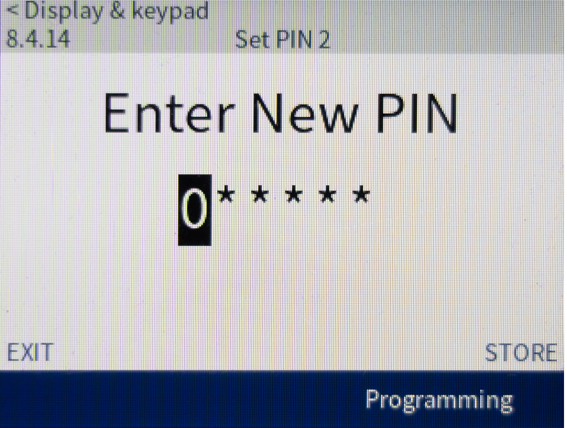
8.4.12 HMI PIN 1
Sets a 6-digit PIN to unlock the display.
| Range: | |
|---|---|
|
000000–999999 |
000000 (default) |

8.4.13 PIN 2 Access Rights
|
Options |
|
|---|---|
|
PIN 2 disabled (default) |
Allows the user to view and modify parameter settings when parameter 1.9 PIN Access Policy is set to ‘Parameters locked’ or ‘Params and Tools locked’. |
|
Access rights to Tools |
Allows the user to access the Tools menu, including simulation tests and BLE pairing when parameter 1.9 PIN Access Policy is set to ‘Tools locked’ or ‘Params and Tools locked’. |
|
Unlocks tools and parameters |
Allows the user can view and modify the parameter settings, and access the Tools menu, including simulation tests and BLE pairing when 1.9 PIN Access Policy is set to ‘Parameters locked’, ‘Tools locked’, or ‘Params and Tools locked’. |
|
PIN 2 disabled (default) |
The stored PIN number (including factory default 000000) is ignored. |
9. Process Functions
9.1 Flags
The flag can signal the situation to external equipment via one of the programmable outputs.
9.1.1 Low Current
Sets the level at which the low current flag operates, as a percentage of motor full load current.
| Range: | |
|---|---|
|
1–100% FLA |
50% FLA (default) |
9.1.2 High Current
Sets the level at which the high current flag operates, as a percentage of motor full load current.
| Range: | |
|---|---|
|
50–700% FLA |
100% FLA (default) |
9.1.3 Motor 1 Overload
The starter has a motor overload flag to give early indication of abnormal operation. The flag can indicate that the motor is operating above its normal loading conditions but lower than the overload limit.
| Range: | |
|---|---|
|
0–160% FLA |
80% FLA (default) |
9.1.4 Motor 2 Overload
The starter has a motor overload flag to give early indication of abnormal operation. The flag can indicate that the motor is operating above its normal loading conditions temperature but lower than the overload limit.
| Range: | |
|---|---|
|
0–160% FLA |
80% FLA (default) |
9.1.5 Underpower
Sets the level at which the underpower flag operates, as a percentage of rated power. Set as required.
| Range: | |
|---|---|
|
1–100% kW/hp |
50% kW/hp (default) |
9.1.6 Overpower
Sets the level at which the overpower flag operates, as a percentage of rated power. Set as required.
| Range: | |
|---|---|
|
1–160% kW/hp |
150% kW/hp (default) |
9.2 Slow Speed
9.2.1 – Slow speed enable
9.2.2 – Slow speed settings 1
9.2.3 – Slow speed settings 2
These parameters do not apply to this release.
9.3 Auto-Reset
9.3.1 – Auto-reset enable
9.3.2 – Auto-reset count
9.3.3 – Auto-reset delay
These parameters do not apply to this release.
9.4 Heater/Anti-Windmill
9.4.1 – Heater/anti-windmill mode
9.4.2 – Heater/anti-windmill level
These parameters do not apply to this release.
10. Productivity
10.1 – Start power baseline
10.2 – Start power alert level
10.3 – Loaded state threshold
10.4 – Operating power baseline
10.5 – Operating power alert level
These parameters do not apply to this release.
11. Advanced
11.1 – 11.6 Parameters
11.1 – Adaptive multi-pump
11.2 – Adaptive control gain
11.3 – Adaptive tracking gain
11.4 – Adaptive pedestal detect
These parameters do not apply to this release.
11.5 – TruTorque acceleration gain
Adjusts the gain for the PID controller used when starting the motor in TruTorque mode.
| Range: | |
|---|---|
|
20–500% |
100% (default) |
11.6 – TruTorque deceleration gain
Adjusts the gain for the PID controller used when stopping the motor in TruTorque mode.
| Range: | |
|---|---|
|
20–500% |
100% (default) |
11.7 Current Control Gain
Adjusts the gain for the PID controller when starting the motor in current ramp mode.
| Range: | |
|---|---|
|
20–500% |
100% (default) |
11.8 Power Ramp Gain
Adjusts the gain for the PID controller used when starting the motor in power ramp mode.
| Range: | |
|---|---|
|
20–500% |
100% (default) |
11.9 Faulty SCR Detection Mode
This parameter does not apply to this release.
11.10 Faulty SCR Detection Delay
Sets the delay before the starter will declare any of the trips ‘L1-T1 shorted’ to ‘L3-T3 shorted’ through ‘L1-T1 open’ to ‘L3-T3 open’ once an abnormal power stack condition occurs. See Trip Messages for details.
11.11 Electro-Mechanical Transition Level
Sets the level of motor current for the starter to transition from wye to delta, as a percentage of full load current.
| Range: | |
|---|---|
|
30–350% |
85% (default) |
11.12 Motor 1 UTS Detection Level
Sets the level that motor current must reduce to during a start, for the starter to transition to running with the bypass contactor closed. This parameter applies to current control, power and TruTorque ramps.
| Range: | |
|---|---|
|
80–500% |
175% (default) |
11.13 Motor 2 UTS Detection Level
Sets the level that motor current must reduce to during a start, for the starter to transition to running with the bypass contactor closed. This parameter applies to current control, power and TruTorque ramps.
| Range: | |
|---|---|
|
80–500% |
175% (default) |
11.14 Bypass Feedback Delay
Sets the starter to match the bypass contactor closing/opening time. Set slightly longer than the maximum closing time, according to the specifications of the bypass contactor used. If this time is too short, the starter will trip on ‘Bypass contactor fail.’
| Range: | |
|---|---|
|
100–10000 milliseconds |
400 ms (default) |
11.15 Main Feedback Delay
Sets the starter to match the main contactor closing/opening time. Set according to the specifications of the contactor used. If this time is too short, the starter will trip on ‘Main contactor fail.’
| Range: | |
|---|---|
|
100–10000 milliseconds |
400 ms (default) |
11.16 PFCC Feedback Enable
Selects whether the starter will monitor the PFCC feedback input (MCM: D10).
| Options: | |
|---|---|
|
Disabled |
(default) |
|
Enabled |
|
11.17 PFCC Feedback Delay
Sets the delay before the starter will monitor the PFCC contactor feedback input (MCM: D10), if enabled.
| Range: | |
|---|---|
|
100–10000 milliseconds |
400 ms (default) |
11.18 Ramp Undercurrent Enable
Enables or disables low current protection while ramping.
If enabled, the starter will trip if the current is below the programmed level while the starter is starting.
| Options: | |
|---|---|
|
Disabled |
(default) |
|
Enabled |
|
11.19 Ramp Undercurrent Level
Sets the trip point for the ramp undercurrent protection, as a percentage of motor full load current.
| Range: | |
|---|---|
|
1–40% FLA |
10% FLA (default) |
11.20 Ramp Undercurrent Delay
Sets a delay for the ramp undercurrent protection. The current must be below the trip threshold for longer than the delay, while the starter is ramping.
| Range: | |
|---|---|
|
100–90000 milliseconds |
1000 ms (default) |
11.21 Current at Stop Enable
Enables or disables current at stop protection.
If enabled, the starter will trip if current is detected while the starter is stopped or not ready.
| Options: | |
|---|---|
|
Disabled |
(default) |
|
Enabled |
|
11.22 Current at Stop Level
Sets the trip point for current at stop protection, as a percentage of motor full load current.
| Range: | |
|---|---|
|
10–50% FLA |
50% FLA (default) |
11.23 Current at Stop Delay
Sets a delay for the current at stop protection. The current must be above the trip threshold for longer than the delay.
| Range: | |
|---|---|
|
100–90000 milliseconds |
1000 ms (default) |
11.24 Brake Feedback Delay
This parameter is not available in this release.
| Range: | |
|---|---|
|
100–10000 milliseconds |
400 ms (default) |
11.25 MCM Aux Trip Enable
Selects whether the MCM will trip when the digital input is active (MCM:D7).
| Options: | |
|---|---|
|
Disabled |
(default) |
|
Enabled |
|
11.26 Calibrations
11.26.1 Current Calibration
If the starter is reading current too low, increase the calibration factor. If it is reading too high, decrease the calibration factor.
| Range: | |
|---|---|
|
85–115% |
100% (default) |
11.26.3 Power Factor Calibration
The calibration factor adjusts the power factor by changing the blend of Watt and VAR while leaving the VA unchanged. If the starter is reading power factor too lagging, increase the calibration factor. If it is reading too leading, decrease the calibration factor.
| Range: | |
|---|---|
|
0.85–1.15% |
1.00% (default) |
11.27 Power Loss Ride-Through
Power loss ride-through sets the delay before tripping on a power loss trip if the 3-phase power is lost.
11.27.1 Ride-Through Enable
Selects whether the starter will permit power loss ride-through operation.
| Options: | |
|---|---|
|
Disabled |
(default) |
|
Enabled |
|
11.27.2 Ride-Through Fault Time
Sets the duration for the starter to wait for power to be restored after an unexpected outage. If power is not restored within the fault time, the starter will trip on ‘Ride-through timeout.’
| Range: | |
|---|---|
|
00:01–02:00 (mm:ss) |
00:01 mm:ss (default) |
11.27.3 Contactor Hold Time
If the starter is up to speed and bypassed, contactor hold time sets the duration for the starter to hold the bypass contactor closed, if power is lost.
| Range: | |
|---|---|
|
00:00–00:10 (mm:ss) |
00:00 mm:ss (default) |
11.27.4 Recovery Mode
Selects which start mode the starter will use to restart the motor after power loss ride-through operation.
| Options: | |
|---|---|
|
Fast recovery (default) |
Current acceleration ramp from 100 - 800% FLA with a ramp time of 1 second. |
|
Voltage ramp |
Voltage acceleration ramp using 4.1.4 Ramp Time parameter settings. |
|
Current ramp |
Current acceleration ramp using 4.1.4 Ramp Time parameter settings. |
11.28 Factory
11.28.1 Model Code
| Options: | |
|---|---|
| Displays the starter's model code on the screen. | End users cannot edit this parameter. This parameter is preset in the factory. |
11.28.2 Serial Number
| Options: | |
|---|---|
| Displays the starter's serial number on screen. | End users cannot edit this parameter. This parameter is preset in the factory. |
1.28.3 Phase 1: Part Number
| Options: | |
|---|---|
| Sets the starter's phase arm part number. | End users cannot edit this parameter. This parameter is preset in the factory. |
11.28.4 Phase 1: Serial Number
| Options: | |
|---|---|
| Sets the starter's phase arm serial number. | End users cannot edit this parameter. This parameter is preset in the factory. |
11.28.5 Phase 2: Part Number
| Options: | |
|---|---|
| Sets the starter's phase arm part number. | End users cannot edit this parameter. This parameter is preset in the factory. |
11.28.6 Phase 2: Serial Number
| Options: | |
|---|---|
| Sets the starter's phase arm serial number. | End users cannot edit this parameter. This parameter is preset in the factory. |
11.28.7 Phase 3: Part Number
| Options: | |
|---|---|
| Sets the starter's phase arm part number. | End users cannot edit this parameter. This parameter is preset in the factory. |
11.28.8 Phase 3: Serial Number
| Options: | |
|---|---|
| Sets the starter's phase arm serial number. | End users cannot edit this parameter. This parameter is preset in the factory. |
11.28.10 SCR Itsm
| Options: | |
|---|---|
| Sets the SCR current surge rating This parameter is preset in the factory. | End users cannot edit this parameter. |
11.28.11 Stack Temperature Sensor Type
| Options: | |
|---|---|
| Sets the type of sensor installed on the power stack. | This parameter is preset in the factory. |
11.28.12 Stack Trip Temperature
| Options: | |
|---|---|
| Sets the temperature above which the power stack will trip on overtemperature if the power stack is fitted with a sensor. | This parameter is preset in the factory. |
11.28.13 Controller Mode
Indicates how the starter will control the motor. This parameter is preset in the factory.
| Options: | |
|---|---|
|
Soft starter: 3-phase |
The starter will operate as a 3-phase soft starter. |
|
Soft starter: 2-phase |
The starter will operate as a 2-phase soft starter. This function is not available in this release. |
|
ATL starter |
The starter can only operate as a across-the-line (ATL, also called direct-on-line DOL) starter. |
|
Full voltage mode |
The starter can only operate as an across-the-line (ATL, also called direct on-line DOL) starter. See the Smart ATL user manual for details. |
|
Wye/delta starter |
The starter can only operate as a Wye/Delta starter (also known as star-delta). |
|
Configuration incomplete |
|
|
Description |
Options |
|
|---|---|---|
|
Indicates how the starter will control the motor. The integrator must set this parameter. This parameter cannot be edited by end users. |
Soft Starter: 3-phase |
The starter will operate as a 3-phase starter. |
|
Soft Starter: 2-phase |
The starter will operate as a 2-phase starter. This function is not available in this release of the product. |
|
|
Full voltage mode |
The starter can only operate as an across-the-line (ATL, also called direct on-line DOL) starter. See the Smart ATL starter manual for details. |
|
|
Wye/Delta starter |
The starter can only operate as a Wye/Delta starter (also known as star-delta). |
|
11.28.14 CT Primary
| Options: | |
|---|---|
| Sets the primary current input rating of the CT. | This parameter is preset in the factory. |
11.28.15 Voltage Sensor Type
Sets the voltage sensor type. This parameter is preset in the factory.
| Options: |
|---|
|
Voltage divider |
|
Voltage transformer |
|
Configuration incomplete |
11.28.16 VT Primary
| Options: | |
|---|---|
| Sets the VT primary, if parameter No 11.28.15 Voltage Sensor Type is set to ‘Voltage transformer. | This parameter is preset in the factory. |
11.28.18 Main Contactor
Sets the position and control functionality of the main contactor. This parameter is preset in the factory.
| Options: | |
|---|---|
|
Externally controlled MC |
The starter does not control the main contactor. |
|
Before bypass, no feedback |
The main contactor is located before (upstream of) the bypass contactor and does not have a feedback output. |
|
Before bypass, with feedback |
The main contactor is located before (upstream of) the bypass contactor and has a feedback output. |
|
Inside bypass, no feedback |
The main contactor is located after (downstream of) the bypass contactor and does not have a feedback output. |
|
Inside bypass, with feedback |
The main contactor is located after (downstream of) the bypass contactor and has a feedback output. |
|
Configuration incomplete |
|
20. Fieldbus Modules
Use the parameters in Parameter Groups 20 Fieldbus Modules to configure the communications modules.
For the parameters in this group, please see the manual supplied with the module.
40. Accessory Modules
For the parameters in this group, please see the manual supplied with the module.
100. Fitted Modules
The parameters in this group indicate whether the listed accessory is fitted or not. These are read-only.
100.1 – 3.5'' display fitted
| Options: |
|---|
|
Not installed |
|
Installed |
100.2 – 7'' display fitted*
| Options: |
|---|
|
Not installed |
|
Installed |
100.3 – Modbus fitted
| Options: |
|---|
|
Not installed |
|
Installed |
100.4 – Profibus fitted*
| Options: |
|---|
|
Not installed |
|
Installed |
100.5 – DeviceNet fitted
| Options: |
|---|
|
Not installed |
|
Installed |
100.6 – Modbus TCP fitted
| Options: |
|---|
|
Not installed |
|
Installed |
100.7 – ProfiNet fitted
| Options: |
|---|
|
Not installed |
|
Installed |
100.8 – EtherNet/IP fitted
| Options: |
|---|
|
Not installed |
|
Installed |
100.9 – RTD 1 fitted
| Options: |
|---|
|
Not installed |
|
Installed |
100.10 – RTD 2 fitted
| Options: |
|---|
|
Not installed |
|
Installed |
100.11 – RTD 1 expansion fitted
| Options: |
|---|
|
Not installed |
|
Installed |
100.12 – IO 1 fitted*
| Options: |
|---|
|
Not installed |
|
Installed |
100.13 – IO 2 fitted*
| Options: |
|---|
|
Not installed |
|
Installed |
100.14 – Pumping Module fitted*
| Options: |
|---|
|
Not installed |
|
Installed |