Install the Dry Contact I/O SmartSlot Card
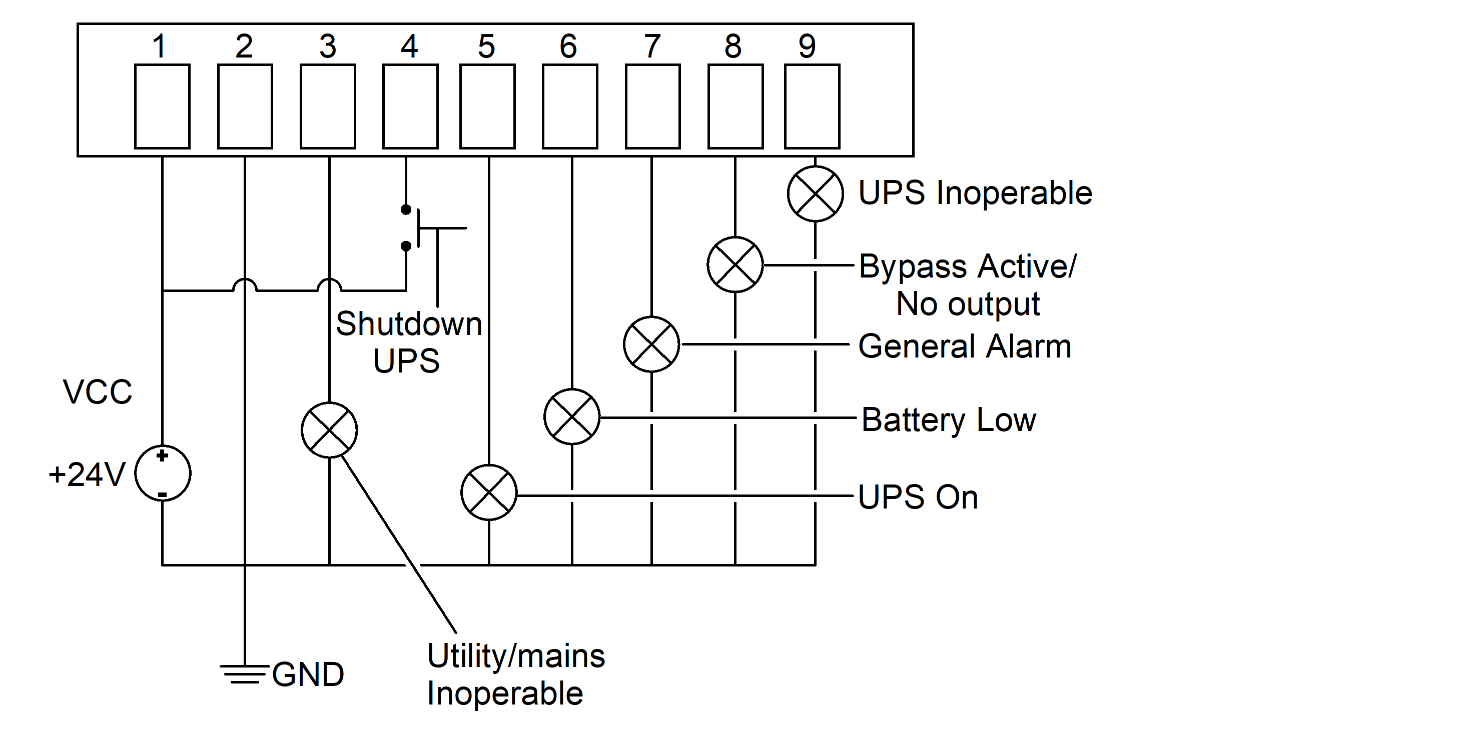
Characteristics of output contacts (pin 3, 5 – 9):
-
Permissible voltage: 24 V
-
Permissible current: 1 A
Definitions of Output Contacts (Pin 3, 5 – 9)
|
Pin |
Pin name |
Description |
|---|---|---|
|
3 |
Utility/mains unavailable |
Utility/mains is unavailable. Active: low |
|
5 |
UPS on |
UPS is in normal mode. Active: low |
|
6 |
Battery low |
Battery voltage reaches EOD. Active: low |
|
7 |
General alarm |
UPS gives off general alarm such as input out of tolerance, battery low, manual bypass, or output overload. Active: low |
|
8 |
Bypass active or No output |
UPS is in bypass mode, or there is no output power to load. Active: low |
|
9 |
UPS inoperable |
UPS is inoperable in cases of REC inoperable, INV inoperable or Bypass inoperable. Active: low |
Characteristics of input contact (pin 4):
-
Permissible voltage: 24 V
-
Permissible current: 80 mA
-
Reverse max voltage: 6 V
Definitions of Input Contact (Pin 4)
|
Pin |
Pin name |
Description |
|---|---|---|
|
4 |
Shut down UPS |
UPS can be shut down by energizing this pin with external power supply for at least two seconds. |
Definitions of Other Contacts (Pin 1, 2)
|
Pin |
Pin name |
Description |
|---|---|---|
|
1 |
VCC |
Power supply common for output contacts. Must apply external power supply max 24 V to pin 1 and pin 2. |
|
2 |
GND |
Common ground for external power supply and input/output signal. |
- Assemble the dry contact I/O SmartSlot card:
- Add the black protective film to the front bracket.

- Install the PCBA board on the front bracket and fasten with the screw provided. Torque
to 0.49 Nm (0.37 lb-ft/4.33 lb-in).

- Add the black protective film to the front bracket.
- Remove the SmartSlot cover from the rear panel of the UPS.
Rear View

- Insert the dry contact I/O SmartSlot card into the SmartSlot and fix with the screws.
Torque to 0.49 Nm (0.37 lb-ft).
Rear View

- Follow the diagram, connect the 22 AWG signal cable to the 9-pin female connector
provided. Connect the 9-pin female connector to the dry contact card.NOTE: Route the signal cables separately from the power cables.
Rear View