Top and Bottom Conduit Entrance Dimensions–Not for Construction
(consult factory drawings)
Top Conduit Entrance–Auxiliary Section (22-inch wide)

Bottom Conduit Entrance–Auxiliary Section (22-inch wide)

Top Conduit Entrance–Auxiliary Section (30-inch wide)

Bottom Conduit Entrance–Auxiliary Section (30-inch wide)

Top Conduit Entrance–Auxiliary Section (36-inch wide)

Bottom Conduit Entrance–Auxiliary Section (36-inch wide)

Top Conduit Entrance–Main, Tie, and Feeder Sections
(22-inch wide)

NOTE: Top conduit entrance area is reduced when close-coupled with
a transformer.
Bottom Conduit Entrance–Main, Tie, and Feeder Sections
(22-inch wide)

Top Conduit Entrance–Main, Tie, and Feeder Sections
(30-inch wide)

NOTE: Top conduit entrance area is reduced when close-coupled with
a transformer.
Bottom Conduit Entrance–Main, Tie, and Feeder Sections
(30-inch wide)

Top Conduit Entrance–Main, Tie, and Feeder Sections
(36-inch wide)

NOTE: Top conduit entrance area is reduced when close-coupled with
a transformer.
Bottom Conduit Entrance–Main, Tie, and Feeder Sections
(36-inch wide)

Front Elevation Dimensions–Not for Construction (consult
factory drawings)
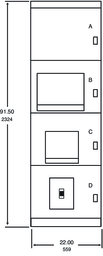
Typical Auxiliary Section
(22-inch wide)

Typical Auxiliary Section (22, 30, and 36–inch wide)
| Location |
Description |
| AB |
Blank
or instrument |
| CD |
Blank
or instrument |
Typical Mains Circuit Breakers (22-inch wide)

Typical Mains Circuit Breakers (22–inch wide)
| Location |
Description |
Frame Size |
Frame SCCR |
| A |
Blank
or instrument |
— |
— |
| B |
Main |
800–2000
A |
NW-N,
H, L, LF |
| C, D |
Feeder |
800–1200
A |
NT-N,
H, L1, L, LF |
| C, D |
Feeder |
600
A |
D-N,
H, L |
| C, D |
Feeder |
800–2000
A |
NW-N,
H, L, LF |
Typical Mains Circuit Breakers (22-inch wide)

Typical Mains Circuit Breakers (22–inch wide)
| Location |
Description |
Frame Size |
Frame SCCR |
| A |
Blank
or instrument |
— |
— |
| BC |
Main |
2500–3000
A |
H,
L |
| D |
Feeder |
800–2000
A |
NW-N,
H, L, LF |
| 800–1200
A |
NT-N,
H, L1, L, LF |
| 600
A |
D-N,
H, L |
NOTE: Any main, tie, or feeder compartment positions may be used as
a blank, or instrument compartment. Not convertible for future circuit
breaker use. Height including secondary wiring trough compartment
is 93.7 inches (2380 mm).
Typical Mains Circuit Breakers (36–inch wide)

Typical Mains Circuit Breakers (36-inch wide)
| Location |
Description |
Frame Size |
Frame SCCR |
| A |
Blank
or instrument |
— |
— |
| BC |
Mains |
4000–5000
A |
H,
L |
| D |
Feeder |
800–2000
A |
NW-
N, H, L, LF |
| (2)
800–1200 A |
NT-
N, H, L1, L, LF |
Typical Feeder Circuit Breakers
(22-inch wide)

Typical Feeder Circuit Breakers (22-inch wide)
| Location |
Description |
Frame Size |
Frame SCCR |
| A, B, C, D |
Feeder |
800–2000
A |
NW-
N, H, L, LF |
| A, B, C, D |
Feeder |
800–1200
A |
NT-
N, H, L1, L, LF |
| A, B, C, D |
Feeder |
400–600
A |
D-
N, H, L |
| B, C, D |
Feeder |
(2)
150–250 A |
H
or J-G, J, L |
NOTE: Any main, tie, or feeder compartment positions may be used as
a blank, or instrument compartment. Not convertible for future circuit
breaker use. Height including secondary wiring trough compartment
is 93.7 inches (2380 mm).
Typical Feeder Circuit Breakers
(22-inch wide)

Typical Feeder Circuit Breakers (22-inch wide)
| Location |
Description |
Frame Size |
Frame SCCR |
| AB |
Feeder |
2500 A |
NW- H, L |
| BC |
Feeder |
| CD |
Feeder |
| BC |
Feeder |
3000 A |
NW- H, L |
| CD |
Feeder |
| D |
Feeder |
800–2000
A |
NW-
N, H, L, LF |
| 800–1200
A |
NT-
N, H, L1, L, LF |
| 400–600
A |
D-
N, H, L |
| (2)
150–250 A |
H
or J-G, J, L |
Typical Feeder Circuit Breakers
(30–inch
wide)

Typical Feeder Circuit Breakers (30-inch wide)
| Location |
Description |
Frame Size |
Frame SCCR |
| A, B, C, D |
Feeder |
800–2000
A |
NW-
N, H, L, LF |
| B, C, D |
Feeder |
(4)
150–250 A |
H
or J-G, J, L |
| A, B, C, D |
Feeder |
(2)
400–600 A |
D-
N, H, L |
| A, B, C, D |
Feeder |
800–1200
A |
NT-
N, H, L1, L, LF |
NOTE: Any main, tie, or feeder compartment positions may be used as
a blank, or instrument compartment. Not convertible for future circuit
breaker use. Height including secondary wiring trough compartment
is 93.7 inches (2380 mm).
Typical Feeder Circuit Breakers
(36-inch wide)

Typical Feeder Circuit Breakers (36-inch wide)
| Location |
Description |
Frame Size |
Frame SCCR |
| AB, BC, CD |
Feeder |
2500–4000
A |
NW-
H, L |
| A, B, C, D |
Feeder |
(2)
800–1200 A |
NT-
N, H, L1, L, LF |
| A, B, C, D |
Feeder |
(2)
400–600 A |
D-
N, H, L |
NOTE: Any main, tie, or feeder compartment positions may be used as
a blank, or instrument compartment. Not convertible for future circuit
breaker use. Height including secondary wiring trough compartment
is 93.7 inches (2380 mm).
NEMA 3R Walk-in Low Voltage Switchboard/Switchgear Top Conduit
Entrance Dimensions–Not for Construction (consult factory drawings)

NEMA 3R Walk-in Low Voltage Switchboard/Switchgear Bottom Conduit
Entrance Dimensions–Not for Construction (consult factory drawings)

NOTE: Dimensions–Not for Construction (consult factory drawings).
Front View, NEMA 3R Walk-in Low Voltage Switchboard/Switchgear

Right Side View, NEMA 3R Walk-in Low Voltage Switchboard/Switchgear

