
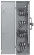
Double-Throw Safety Switches
30-100 A Types DT, DTU (Series F)
 |
 |
|
30–100 A DT, DTU (Series F) Type 1 |
|
-
Fusible (DT) and non-fusible (DTU) switches available
-
Manual transfer of a load between two power sources (or one power source between two loads on series A, F DT & DTU only)
-
Standards: UL 98, Type KS1, CSA C22.2 No. 4
-
Modular design–switch handle, lock-plate, switch mechanism; line and load bases are field replaceable.
-
Load make/break rated
-
Horsepower rated
-
Dual cover interlock
-
May be padlocked ON (I) or OFF (O)
-
Lock-off accepts up to three padlocks
-
Padlock provisions in the center “OFF” position.
-
Padlock provisions in the “ON” positions
-
Side-opening door
-
Quick make / quick break mechanism
-
Meets NEMA requirements as heavy duty switch
-
Field-installed electrical interlock kits
-
Field-installed neutral assembly kits (Two–pole and three–pole switches)
-
Supplied as standard for switching one load between two power sources, and may be field-converted to switch one power source between two loads.
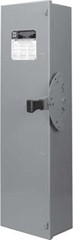
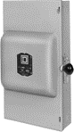
30 (Series T4), 200–600 A Types 82,000 and 200 A DTU (Series E, A)
 |
|
82,000 Line Type 1 |
-
Non-fusible
-
Designed for manual transfer of one load between two power sources
-
82,000 and DTU double throw switches are continuous duty rated for their nameplate ampere rating.
-
The 82,000 and DTU (Series E, A) switches are load make/break rated
-
Horsepower rated only as footnoted.
Field-Installable Accessories
-
Neutral
-
Interlock
-
Grounding Terminals
Double–Throw Fusible and Non-Fusible 240 Vac
Double Throw–Fusible and Non-Fusible 240 Vac, Two-Pole and Three-Pole and Four-Pole
|
System |
Amperes |
Series |
Type 1 |
Type 3R |
Type 12 |
||||||
|---|---|---|---|---|---|---|---|---|---|---|---|
|
240 Vac |
250 Vdc* |
||||||||||
|
Std. |
Max |
Std. |
Max. |
||||||||
|
1Ø |
3Ø |
1Ø |
3Ø |
||||||||
| Fusible Two–Pole, 240 Vac–250 Vdc | |||||||||||
|
100 |
F |
– |
7-1/2 |
15* |
15 |
30* |
– |
20 |
|||
| Non-Fusible Two–Pole, 240 Vac | |||||||||||
|
30 |
T4 |
– |
– |
– |
– |
– |
– |
– |
– |
||
|
200 |
E |
– |
– |
15 |
– |
– |
– |
– |
– |
||
|
400 |
A |
– |
– |
– |
– |
– |
50 |
– |
|||
|
60 |
F |
– |
– |
– |
– |
10 |
15 |
– |
10 |
||
|
100 |
– |
– |
– |
15 |
– |
– |
20 |
||||
| Fusible Three–Pole, 240 Vac–250 Vdc | |||||||||||
|
30 |
F |
– |
– |
1.5* |
3* |
3* |
7-1/2* |
– |
5 |
||
|
60 |
– |
3* |
7-1/2* |
10* |
15* |
– |
10 |
||||
|
100 |
– |
7-1/2* |
15* |
15* |
30* |
– |
20 |
||||
| Non-Fusible Three–Pole, 240 Vac–250 Vdc | |||||||||||
|
30 |
F |
– |
– |
– |
3 |
5* |
10* |
– |
5 |
||
|
60 |
– |
– |
– |
– |
10* |
15* |
– |
10 |
|||
|
100 |
– |
– |
– |
15* |
– |
– |
20 |
||||
|
30 |
T4 |
– |
– |
– |
– |
– |
– |
– |
– |
||
|
200 |
E |
– |
15 |
– |
– |
– |
– |
||||
|
400 |
A |
– |
– |
125 |
– |
– |
50 |
– |
|||
|
600 |
– |
– |
125 |
– |
– |
50 |
– |
||||
| Non-Fusible Four–Pole, 240 Vac | |||||||||||
|
600 |
A |
– |
– |
125 |
– |
– |
50 |
– |
|||
Double–Throw Fusible and Non-Fusible 600 Vac
Fusible Three–Pole, 600 Vac–600 Vdc
|
System |
Amperes | Series |
Type 1 |
Type 3R |
Type 4,4X,5 |
Type 12 Gasketed |
||||||||
|---|---|---|---|---|---|---|---|---|---|---|---|---|---|---|
|
240 Vac |
480 Vac |
600 Vac |
Vdc * |
|||||||||||
|
Std. |
Max. |
Std. |
Max. |
Std. |
Max. |
250 |
600 |
|||||||
|
3Ø |
3Ø |
3Ø |
3Ø |
3Ø |
3Ø |
|||||||||
|
30 |
F |
– |
– |
3 |
7-1/2 |
5 |
15 |
7-1/2 |
20 |
– |
– |
|||
|
60 |
F |
– |
– |
7-1/2 |
15 |
15 |
30 |
15 |
50 |
– |
– |
|||
|
100 |
F |
– |
– |
15 |
30 |
25 |
60 |
30 |
75 |
20 |
50* |
|||
Non-Fusible Three–Pole, 600 Vac–600 Vdc
|
System |
Amperes | Series |
Type 1 |
Type 3R |
Type 4,4X,5 |
Type 12 Gasketed |
|||||||
|---|---|---|---|---|---|---|---|---|---|---|---|---|---|
|
240 Vac |
480 Vac |
600 Vac |
Vdc * |
||||||||||
|
Max. |
Max. |
Max. |
Max. |
Max. |
Max. |
250 |
|||||||
|
1Ø* |
3Ø |
1Ø* |
3Ø* |
1Ø* |
3Ø |
||||||||
|
30 |
F |
– | – |
5 |
10 |
7-1/2 |
20 |
10 |
30 |
– |
|||
|
60 |
F |
10 |
20* |
25 |
50* |
30 |
60* |
– |
|||||
|
100 |
F |
20 |
40* |
40 |
75* |
40 |
75* |
– |
|||||
|
200 |
E |
– |
– |
– |
– |
– |
– |
– |
– |
||||
|
400 |
A |
– |
125* |
– |
250* |
– |
350* |
50* |
|||||
|
600 |
A |
– |
– |
125* |
– |
250* |
– |
350* |
50* |
||||
Non-Fusible Four–Pole, 600 Vac–600 Vdc
|
System |
Amperes | Series |
Type 1 |
Type 3R |
Type 4,4X,5 |
Type 12 Gasketed |
||||||||
|---|---|---|---|---|---|---|---|---|---|---|---|---|---|---|
|
240 Vac |
480 Vac |
600 Vac |
Vdc * |
|||||||||||
|
Max. |
Max. |
Max. |
Max. |
Max. |
Max. |
250 |
600 |
|||||||
|
60 |
F |
Use Type 12 |
20 |
20 |
40 |
50 |
50 |
60 |
10 |
30 |
||||
|
100 |
F |
Use Type 12 |
30 |
40 |
50 |
75 |
50 |
75 |
20 |
50 |
||||
|
400 |
A |
– | – |
– |
125* |
– |
250* |
– |
350* |
– |
– |
|||
|
600 |
A |
– | – |
– |
125* |
– |
250* |
– |
350* |
– |
– |
|||
Non-Fusible Six–Pole, 600 Vac–600 Vdc
|
System |
Amperes | Series |
Type 3R |
Type 4,4X,5 |
Type 12 Gasketed |
||||||||
|---|---|---|---|---|---|---|---|---|---|---|---|---|---|
|
240 Vac |
480 Vac |
600 Vac |
Vdc* |
||||||||||
|
Std. |
Max. |
Std. |
Max. |
Std. |
Max. |
250 |
600 |
||||||
|
60 |
F |
– |
– |
20 |
20 |
40 |
50 |
50 |
60 |
10 |
30 |
||
|
100 |
F |
– |
– |
30 |
40 |
50 |
75 |
50 |
75 |
20 |
50 |
||
Accessories and Lug Data
Electrical Interlocks
EIK1 |
Electrical interlocks for Double Throw Safety Switches are available in kit form for field installation. Each kit contains instructions for proper field mounting.
For Electrical Interlock Contact Ratings, see Electrical Interlock Contact Ratings .
Neutral Assemblies Kits
Neutral Assemblies
| Switch | Field-Installed
Standard Neutral Kit Cat. No. |
Terminal Data AWG / kcmil |
Field-Installed
Copper only Neutral Kit Cat. No. |
Terminal Data AWG / kcmil |
|---|---|---|---|---|
|
30–100
A Type DT, DTU |
(3) 14-1/0 Al / Cu plus (2) 14-6 Al / Cu Svc Ground |
(3) 14-1/0 Cu plus |
||
|
(2) 14-6 Cu Svc Ground |
||||
|
30 A |
(3) 14-4 Al / Cu plus (2) 14-4 Al / Cu Svc Ground |
– |
– |
|
|
200 A Type
82000 |
(3) 6-300 Al / Cu (1) 6-2/0 Al or 10-2/0 Cu Svc Ground |
|||
|
400 A Type
DTU |
(1) 1/0-720 Al / Cu or (2) 1/0-300 Al / Cu plus (2) 6-250 Al / Cu Svc Ground |
|||
|
600 A Type
DTU |
(6) 250-500 Al / Cu plus (1) 6-250 Al / Cu Svc Ground |
Grounding Kits
Grounding Kits
| Switch | Grounding Lug Kit Cat. No. | Terminal Data AWG / kcmil |
|---|---|---|
|
30–60 A Type DT, DTU |
Included |
(3) 14-2 Al / Cu or (6) 14-10 Al / Cu |
|
100 A Type DT, DTU |
Included |
(3) 14–1/0 Al / Cu |
|
30 A Type 92,000 |
(4) 14-4 Al / Cu |
|
|
200 A Type 82000 and DTU |
(3) 14–1/0 Al / Cu |
|
|
400–600 A Type DTU |
(2) 6–250 Al / Cu* |
Class R Fuse Kits
RFK06 RFK10 |
When installed, this kit rejects all but Class R fuses. Kits are available for field installation.
Viewing Windows
Viewing window is not an offer in all double throws, consult with your local distributor to obtain more information.
Lock-ON Provisions
Lock-ON provisions are a standard feature on 30–100 A type DT and DTU (Series F), and type 92000 switches.
Rainproof Bolt-On Hubs for Double Throw Safety Switches
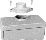 |
All hubs are for indoor or rainproof applications.
Suitable for use with conduit having ANSI standard taper pipe thread.
Type 3R switches with catalog number ending in RB have a bolt-on closing cap factory installed:
-
Accepts 3/4 in. through 2-1/2 in. bolt-on hubs
-
No gaskets required
Type 3R switches with R suffix have blank top endwalls:
-
Accepts 3 in. through 4 in. bolt on hubs
-
Gaskets provided
-
Conduit entry holes must be cut in the field
Water Resistant Hubs
 |
|
Water Resistant Hubs |
-
Suitable for use with conduit having ANSI standard taper pipe thread
-
Water resistant hubs are field installed on Type 4 / 4X / 5 stainless steel and Type 12 / 3R and 12K enclosures
-
Water resistant hubs are available in zinc or chrome plated finish
-
Gaskets provided
Application Data for Double Throw Safety Switches
Diagram 1 |
Diagram 2 |
|
Situations Requiring Fuses
|
|
Maximum Short Circuit Current Ratings
| Switch Type | Amperes | Voltage Rating | UL Listed Fuse Class | Short Circuit Current Rating * (A) |
|---|---|---|---|---|
|
Type 92000 |
30 |
240 V |
H, K |
10,000 * |
|
Type DT (Series F) |
30–100 |
240 V – 600 V |
H, K |
10,000 |
|
R, J |
200,000 |
|||
|
Type DTU * (Series F) |
30–100 |
240 V – 600 V |
H or K |
10,000 * |
|
R, J or T |
200,000 |
|||
|
200 |
240 V |
H, K |
10,000 * |
|
|
DTU324N (Series E) |
200 |
240 V |
R, J |
10,000 |
|
Type 82,000 |
All |
240 V – 600 V |
H, K |
10,000 * |
|
Type DTU (Series A) |
400–600 |
240 V – 600 V |
H, K |
10,000 |
|
R, J or T |
100,000 |
Terminal Lug Data for Double Throw Safety Switches
Terminal Lug Data for Type DT, DTU (Series F) Double Throw Safety Switches *
| Switch Type | Wires per Phase | Type 1, 3R, 4, 4X, 12 |
|---|---|---|
| Standard Lug Wire Range AWG/kcmil | ||
|
30–60 A Type DT, DTU (Series F) |
1 |
12–2 Al |
|
100 A Type DT, DTU (Series F) |
1 |
12–1/0
Al |
Terminal Lug Data for Types 82,000 and for A and E-Series DTU devices *
| Amperes | Wires per Phase | Wire Range Wire Bending Space Per NEC Table 373-6 | Lug Wire Range AWG/kcmil |
|---|---|---|---|
| AWG/kcmil | |||
|
30 A (Series T4) |
1 |
14–8 Al / Cu |
12–2 Al |
|
200 |
1 |
6–300 Al / Cu |
6–300 Al / Cu |
|
400 |
1 |
1/0–600 Al / Cu |
1/0–750 Al / Cu |
|
600 |
2 |
250–500 Al / Cu |
250–500 Al/Cu |
Dimensions for Double Throw Safety Switches
Series F Devices 30–100 A
30–100 A Type DT, DTU (Series F)–Approximate Dimensions
|
Cat. No. |
Series |
H |
W |
W/H |
D |
||||
|---|---|---|---|---|---|---|---|---|---|
|
in. |
mm |
in. |
mm |
in. |
mm |
in. |
mm |
||
|
F5 |
38.00 |
965 |
9.88 |
251 |
11.13 |
283 |
6.75 |
171 |
|
|
F5 |
38.00 |
965 |
6.87 |
174 |
8.12 |
206 |
6.60 |
168 |
|
|
F5 |
38.00 |
965 |
10.25 |
260 |
11.80 |
300 |
6.60 |
168 |
|
|
F5 |
38.00 |
965 |
10.25 |
260 |
11.50 |
292 |
6.75 |
171 |
|
|
F5 |
38.00 |
965 |
10.25 |
260 |
11.80 |
300 |
6.60 |
168 |
|
|
F5 |
38.00 |
965 |
9.88 |
251 |
11.13 |
283 |
6.75 |
171 |
|
|
F5 |
38.00 |
965 |
6.87 |
174 |
8.12 |
206 |
6.60 |
168 |
|
|
F5 |
38.00 |
965 |
10.25 |
260 |
11.50 |
292 |
6.75 |
171 |
|
|
F5 |
38.00 |
965 |
10.25 |
260 |
11.80 |
300 |
6.60 |
168 |
|
|
F5 |
38.00 |
965 |
10.25 |
260 |
11.50 |
292 |
6.75 |
171 |
|
|
F5 |
38.00 |
965 |
10.25 |
260 |
11.80 |
300 |
6.60 |
168 |
|
|
F5 |
38.00 |
965 |
9.88 |
251 |
11.13 |
283 |
6.75 |
171 |
|
|
F5 |
38.00 |
965 |
6.87 |
174 |
8.12 |
206 |
6.60 |
168 |
|
|
F5 |
29.94 |
760 |
10.25 |
260 |
11.96 |
304 |
6.93 |
176 |
|
|
F5 |
29.94 |
760 |
10.25 |
260 |
11.96 |
304 |
6.93 |
176 |
|
|
F5 |
30.50 |
775 |
10.25 |
260 |
11.96 |
304 |
6.93 |
176 |
|
|
F5 |
29.94 |
760 |
10.25 |
260 |
11.96 |
304 |
6.93 |
176 |
|
|
F5 |
29.94 |
760 |
10.25 |
260 |
11.96 |
304 |
6.93 |
176 |
|
|
F5 |
29.94 |
760 |
10.25 |
260 |
11.96 |
304 |
6.93 |
176 |
|
|
F5 |
30.50 |
775 |
10.25 |
260 |
11.96 |
304 |
6.93 |
176 |
|
|
F5 |
29.94 |
760 |
10.25 |
260 |
11.96 |
304 |
6.93 |
176 |
|
|
F5 |
30.50 |
775 |
10.25 |
260 |
11.96 |
304 |
6.93 |
176 |
|
|
F5 |
29.94 |
760 |
10.25 |
260 |
11.96 |
304 |
6.93 |
176 |
|
|
F6 |
29.94 |
760 |
10.25 |
260 |
11.96 |
304 |
6.93 |
176 |
|
|
F6 |
30.26 |
769 |
10.25 |
260 |
11.50 |
292 |
7.12 |
181 |
|
|
F5 |
30.50 |
775 |
10.25 |
260 |
11.96 |
304 |
6.93 |
176 |
|
|
F5 |
29.94 |
760 |
10.25 |
260 |
11.96 |
304 |
6.93 |
176 |
|
|
F6 |
29.94 |
760 |
10.25 |
260 |
11.96 |
304 |
6.93 |
176 |
|
|
F6 |
30.26 |
769 |
10.25 |
260 |
11.50 |
292 |
7.12 |
181 |
|
|
F5 |
30.50 |
775 |
10.25 |
260 |
11.96 |
304 |
6.93 |
176 |
|
|
F5 |
29.94 |
760 |
10.25 |
260 |
11.96 |
304 |
6.93 |
176 |
|
|
F6 |
30.26 |
769 |
15.50 |
394 |
16.75 |
425 |
7.12 |
181 |
|
|
F6 |
30.26 |
769 |
15.50 |
394 |
16.75 |
425 |
7.12 |
181 |
|
|
F5 |
29.94 |
760 |
10.25 |
260 |
11.96 |
304 |
6.93 |
176 |
|
|
F6 |
30.26 |
769 |
15.50 |
394 |
16.75 |
425 |
7.12 |
181 |
|
|
F6 |
30.26 |
769 |
15.50 |
394 |
16.75 |
425 |
7.12 |
181 |
|
|
F6 |
30.26 |
769 |
15.50 |
394 |
16.75 |
425 |
7.12 |
181 |
|
|
F6 |
30.26 |
769 |
15.50 |
394 |
16.75 |
425 |
7.12 |
181 |
|
Series A, E, and T4 Devices
200–600 A Types 82,000 and E-Series DTU and 30 A devices–Approximate Dimensions
|
Cat. No. |
Series |
H |
W |
W/H |
D |
||||
|---|---|---|---|---|---|---|---|---|---|
|
in. |
mm |
in. |
mm |
in. |
mm |
in. |
mm |
||
|
E1 |
32.50 |
826 |
20.63 |
524 |
24.00 |
610 |
10.63 |
270 |
|
|
E2 |
30.88 |
784 |
20.00 |
508 |
23.88 |
607 |
11.75 |
298 |
|
|
E1 |
32.50 |
826 |
20.63 |
524 |
24.00 |
610 |
10.63 |
270 |
|
|
E1 |
30.88 |
784 |
20.00 |
508 |
23.88 |
667 |
11.75 |
298 |
|
|
E1 |
32.50 |
826 |
24.50 |
622 |
26.25 |
667 |
10.63 |
270 |
|
|
E1 |
32.50 |
826 |
24.50 |
622 |
26.25 |
667 |
10.63 |
270 |
|
|
E2 |
32.50 |
826 |
24.50 |
622 |
26.25 |
667 |
10.63 |
270 |
|
|
A1 |
63.31 |
1608 |
23.66 |
601 |
24.46 |
621 |
8.88 |
226 |
|
|
A1 |
63.31 |
1608 |
27.00 |
686 |
27.80 |
706 |
8.88 |
226 |
|
|
A1 |
63.31 |
1608 |
23.66 |
601 |
24.46 |
621 |
8.88 |
226 |
|
|
A1 |
63.31 |
1608 |
27.00 |
686 |
27.80 |
706 |
8.88 |
226 |
|
|
A1 |
63.76 |
1619 |
23.66 |
601 |
24.46 |
621 |
8.88 |
226 |
|
|
A1 |
63.76 |
1619 |
27.00 |
686 |
27.80 |
706 |
8.88 |
226 |
|
|
A1 |
63.76 |
1619 |
23.66 |
601 |
24.46 |
621 |
8.88 |
226 |
|
|
A1 |
63.76 |
1619 |
27.00 |
686 |
27.80 |
706 |
8.88 |
226 |
|
|
A1 |
63.76 |
1619 |
23.66 |
601 |
24.46 |
621 |
8.88 |
226 |
|
|
A1 |
53.81 |
1367 |
23.13 |
588 |
23.88 |
607 |
7.25 |
184 |
|
|
A1 |
53.81 |
1367 |
23.13 |
588 |
23.88 |
607 |
7.25 |
184 |
|
|
A1 |
53.81 |
1367 |
23.13 |
588 |
23.88 |
607 |
7.25 |
184 |
|
|
A1 |
53.81 |
1367 |
23.13 |
588 |
23.88 |
607 |
7.25 |
184 |
|
|
A1 |
53.81 |
1367 |
23.13 |
588 |
23.88 |
607 |
7.25 |
184 |
|
|
A1 |
53.81 |
1367 |
23.13 |
588 |
23.88 |
607 |
7.25 |
184 |
|
|
A1 |
57.50 |
1461 |
23.00 |
584 |
23.75 |
603 |
7.25 |
184 |
|
|
A1 |
57.50 |
1461 |
23.00 |
584 |
23.75 |
603 |
7.25 |
184 |
|
|
A1 |
53.81 |
1367 |
23.13 |
588 |
23.88 |
607 |
7.25 |
184 |
|
|
A1 |
53.81 |
1367 |
23.13 |
588 |
23.88 |
607 |
7.25 |
184 |
|