
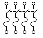
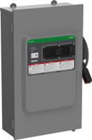
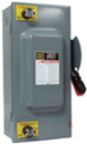
Heavy Duty Safety Switches
|
Type 1 |
Type 3R |
Type 12 |
Type 4, 4x, 5 Stainless Steel |
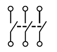
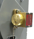
Visible blade heavy duty safety switches are designed for application where maximum performance and continuity of service are required. Heavy duty safety switches feature quick-make, quick-break operating mechanism, a dual cover interlock and a color coded indicator handle. They are suitable for use as service equipment when equipped with a factory-installed neutral assembly and grounding lugs, unless a 600Y/347 V or 480 Y/277 V, 1000 A or greater, solidly grounded Wye system is used. For short circuit current ratings, see Maximum Short Circuit Current Ratings.
240 Volt–Single Throw Fusible Switches
240 Volt–Single Throw Fusible Switches (Suitable for Service Entrance)
| System | Amperes | Type 1* | Type 3R* * | Type 12* * | Type 4X 304 SS* | Service Barriers* | Horsepower Ratings | ||||
|---|---|---|---|---|---|---|---|---|---|---|---|
| Std (Fast Acting One-Time Fuses) | Max (Dual Element Time-Delay Fuses) | 250 Vdc* | |||||||||
| 1Ø | 3Ø* | 1Ø | 3Ø* | ||||||||
| Three–Wire (Two Blade and Fuseholder, One Neutral)–240 Vac 250 Vdc | |||||||||||
| 30 |
Factory Included |
1-1/2 |
3 |
3 |
7-1/2 |
5 |
|||||
| 60 |
3 |
7-1/2 |
10 |
15 |
10 |
||||||
| 100 |
7-1/2 |
15 |
15 |
30 |
20 |
||||||
| 200 |
15 |
25 |
– |
60 |
40 |
||||||
| 400 | – |
– |
50 |
– |
125 |
50 |
|||||
| 600 | – |
– |
75 |
– |
200 |
50 |
|||||
| 800 |
50 |
– |
– |
– |
50 |
||||||
| 1200 |
50 |
– |
– |
– |
50 |
||||||
| Four–Wire (Three Blade and Fuseholder, One Neutral)–240 Vac 250 Vdc | |||||||||||
| 30 |
Factory Included |
1-1/2 |
3 |
3 |
7-1/2 |
5 |
|||||
| 60 |
3 |
7-1/2 |
10 |
15 |
10 |
||||||
| 100 |
7-1/2 |
15 |
15 |
30 |
20 |
||||||
| 200 |
15 |
25 |
– |
60 |
40 |
||||||
| 400 |
– |
50 |
– |
125 |
50 |
||||||
| 600 |
– |
75 |
– |
200 |
50 |
||||||
| 800 |
– |
– |
100 |
– |
250 |
50 |
|||||
| 1200 |
– |
– |
100 |
– |
250 |
50 |
|||||
-
For installing class J fuses:
-
Relocation of the load side fuse base assembly is required in 100–400 A, 240 V switches.
-
Addition of an adapter kit H600J is required in 600 A switches.
-
-
30–600 A 240 V switches accept class R fuses as standard.
600 Volt–Single Throw Fusible Switches
600 Volt–Single Throw Fusible
| System | Amperes | Type 1 | Type 3R* | Type 12* | Type 4X 304 SS* | Service Barriers | Horsepower Ratings | |||||
|---|---|---|---|---|---|---|---|---|---|---|---|---|
| Std (Fast Acting One-Time Fuses) | Max (Dual Element Time-Delay Fuses) | 250 Vdc* | 600 Vdc* | |||||||||
| 480 Vac | 600 Vac | |||||||||||
| 1Ø | 3Ø | 1Ø | 3Ø | |||||||||
| Three–Wire (Three Blade and Fuseholder)–600 Vac 600 Vdc | ||||||||||||
 |
30 |
Factory Included |
3 |
5 |
– |
20 |
5 |
10 |
||||
|
60 |
5 |
15 |
– |
50 |
– |
25 |
||||||
|
100 |
10 |
25 |
– |
75 |
– |
40 |
||||||
|
200 |
25 |
50 |
50 |
150 |
40 |
50 |
||||||
|
400 |
– |
100 |
– |
350 |
50 |
50 |
||||||
|
600 |
– |
150 |
– |
500 |
50 |
50 |
||||||
|
800 |
– |
– |
200 |
– |
500 |
50 |
50 |
|||||
|
1200 |
– |
200 |
– |
500 |
50 |
50 |
||||||
| Four–Wire (Three Blade and Fuseholder, One Neutral)–600 Vac 600 Vdc* | ||||||||||||
 |
30 |
Factory Included |
3 |
5 |
– |
20 |
5 |
15 |
||||
|
60 |
5 |
15 |
– |
50 |
– |
25 |
||||||
|
100 |
10 |
25 |
– |
75 |
– |
40 |
||||||
|
200 |
25 |
50 |
50 |
150 |
40 |
50 |
||||||
|
400 |
– |
100 |
– |
350 |
50 |
50 |
||||||
|
600 |
– |
– |
150 |
– |
500 |
50 |
50 |
|||||
|
800 |
– |
200 |
– |
500 |
50 |
50 |
||||||
|
1200 |
– |
200 |
– |
500 |
50 |
50 |
||||||
-
Provisions for installing class H, R fuses are included in 30–200 A 600 V fusible switches. Relocation of the load side fuse base assembly is required.
-
For installing class J fuses:
-
Relocation of the load side fuse base assembly is required in 400 A, 600 V fusible switches.
-
Addition of an adapter kit H600J is required for 600 A, 600 V fusible switches.
-
600 Volt–Single Throw Non-Fusible Switches
600 Volt–Single Throw Non-Fusible (Not Suitable for Service Entrance)
| System | Amperes | Type 1 | Type 3R* * | Type 12* * | Type 4X 304 SS* | Line Side Barriers | Horsepower Ratings | ||||
|---|---|---|---|---|---|---|---|---|---|---|---|
| 240 Vac | 480 Vac | 600 Vac | 250 Vdc* | 600 Vdc** | |||||||
| Max. 3Ø | Max. 3Ø | Max. 3Ø | |||||||||
| Three–Wire (Three Blade )–600 Vac 600 Vdc | |||||||||||
 |
30 |
Factory Included * |
10 |
20 |
30 |
5 |
15 |
||||
| 60 |
20* |
50* |
60 |
10 |
30 |
||||||
| 100 |
40 |
75* |
100 |
20 |
50 |
||||||
| 200 |
60 |
125 |
150 |
40 |
50 |
||||||
| 400 |
125 |
250 |
350 |
50 |
50 |
||||||
| 600 |
200 |
400 |
500 |
50 |
50 |
||||||
| 800 |
– |
250 |
500 |
500 |
50 |
50 |
|||||
| 1200 |
250 |
500 |
500 |
50 |
50 |
||||||
Four– and Six–Pole Single Throw Switches
Four– and Six–Pole Single Throw Fusible (Not Suitable for Service Entrance)
| System | Amperes | Type 1 | Type 12* | Type 4X | Class R Fuse Kits | Line Side Barriers | Horsepower Ratings Max (Dual Element Time-Delay Fuses) | Vdc Std. (Fast Acting One-time Fuses) | ||||||
|---|---|---|---|---|---|---|---|---|---|---|---|---|---|---|
| 240 V | 480 V | 600 V | 250 Vdc* | 600 Vdc* | ||||||||||
| 2Ø | 3Ø | 2Ø | 3Ø | 2Ø | 3Ø | |||||||||
| Four-Wire (Four Blades and Fuse Holders)–600 Vac 600 Vdc | ||||||||||||||
 |
30 |
Factory Included |
10 |
7-1/2 |
20 |
15 |
25 |
20 |
5 |
10 |
||||
|
60 |
20 |
15 |
40 |
30 |
50 |
50 |
10 |
25 |
||||||
|
100 |
30 |
30 |
50 |
60 |
50 |
75 |
20 |
25 |
||||||
|
200 |
50 |
60 |
– |
125 |
– |
150 |
40 |
50 |
||||||
|
400 |
– |
– |
– |
125 |
– |
250 |
– |
350 |
50 |
50 |
||||
| Six-Wire (Six Blades and Fuse Holders)–600 Vac 600 Vdc | ||||||||||||||
 |
100 |
– |
– |
Factory Included |
– |
30 |
– |
60 |
– |
75 |
– |
– |
||
|
200 |
50 |
60 |
– |
125 |
– |
150 |
40 |
50 |
||||||
Four– and Six–Pole Single Throw Non-Fusible (Not Suitable for Service Entrance)
| System | Amperes | Type 1 | Type 12* | Type 4X | Class R Fuse Kits | Line Side Barriers | Horsepower Ratings Max (Dual Element Time-Delay Fuses) | |||||||
|---|---|---|---|---|---|---|---|---|---|---|---|---|---|---|
| 240 V | 480 V | 600 V | 250 Vdc* | 600 Vdc* | ||||||||||
| 2Ø | 3Ø | 2Ø | 3Ø | 2Ø | 3Ø | |||||||||
| Four-Wire (Four Blades)–600 Vac 600 Vdc | ||||||||||||||
 |
30 |
Factory Included |
10 |
10 |
20 |
20 |
25 |
30 |
10 |
15 |
||||
| 60 |
20 |
20 |
40 |
50 |
50 |
60 |
10 |
30 |
||||||
| 100 |
– |
40 |
– |
75 |
– |
100 |
20 |
30 |
||||||
| 200 |
15 |
60 |
50 |
125 |
50 |
150 |
40 |
50 |
||||||
| 400 | – | – |
– |
– |
– |
– |
– |
350 |
– |
– |
||||
| Six-Wire (Six Blades)–600 Vac 600 Vdc | ||||||||||||||
 |
30 |
– |
– |
Factory Included |
– |
10 |
– |
20 |
– |
30 |
– |
– |
||
|
60 |
– |
– |
– |
20 |
– |
50 |
– |
60 |
– |
– |
||||
|
100 |
– |
– |
40 |
– |
75 |
– |
75 |
– |
– |
|||||
|
200 |
– |
– |
60 |
– |
125 |
– |
150 |
– |
– |
|||||
Maximum Short Circuit Current Ratings–AC
Fusible Safety Switches Ratings
Fusible Safety Switches
|
Heavy Duty Safety Switch Type |
Fuse Class |
Short Circuit Current Ratings |
|---|---|---|
|
Fusible |
H, K |
10 kA |
|
R, J, L |
200 kA * |
Non-Fusible Safety Switches – Ratings
Systems equal or less than 10 kAIR SCCR–Any brand of circuit breaker or fuse not exceeding the ampere rating of the switch may be used in conjunction with a non-fusible safety switch.
Systems above 10 kAIR SCCR–When applied on systems greater than 10 kA short circuit current available, the CSA certified short circuit current rating for Square D non-fusible switches is based upon the switch being used in conjunction with fuses or Square D circuit breakers.
Non-Fusible Safety Switches* *
|
Switch Rating |
Fuse or Circuit Breaker Type* |
Three-Phase |
250 Vdc / 600 Vdc | ||
|---|---|---|---|---|---|
|
240 Vac |
480 Vac |
600 Vac |
|||
|
With Upstream Fuse Protection |
|||||
|
All |
H, K |
10 kA |
10 kA |
10 kA |
Up to 10 kA |
|
R,T,J,L |
200 kA |
200 kA |
200 kA |
||
|
With Upstream Circuit Breaker Protection |
|||||
|
All |
Any brand circuit breaker |
10 kA |
10 kA |
10 kA |
Up to 10 kA |
|
30–100 |
HD |
25 kA |
18 kA |
14 kA |
|
|
HG |
65 kA |
35 kA |
18 kA |
||
|
HJ |
25 kA |
||||
|
HL |
35 kA |
||||
|
HR |
|||||
|
FA |
14 kA |
14 kA |
14 kA |
||
|
FH |
18 kA |
18 kA |
18 kA |
||
|
200 |
HD, JD |
25 kA |
14 kA |
||
|
HG, JG |
65 kA |
35 kA |
18 kA |
||
|
HJ, JJ |
35 kA |
25 kA |
|||
|
HL, JL |
35 kA |
||||
|
HR, JR |
|||||
|
400 |
LA |
22 kA |
22 kA |
22 kA |
|
|
LH |
25 kA |
25 kA |
25 kA |
||
|
400–600 |
LD |
18 kA |
14 kA |
||
|
LG |
65 kA |
35 kA |
18 kA |
||
|
LJ |
100 kA |
65 kA |
25 kA |
||
|
LL |
50 kA |
||||
|
LR |
65 kA |
||||
Special Application Heavy Duty Safety Switches
|
VH361SSGL |
H363DF |
H361DX |
316 Grade Stainless Steel–Type 3, 3R, 4, 4X, 5, 12
VH361SSGL |
316 stainless steel enclosure safety switches offer superior corrosion resistance to a wider range of chemicals than 304 stainless switches. 316 better resists chloride and is often used in marine, waste treatment and transportation applications. Use water resistant hubs, see Water Resistant Hubs. Equipment grounding lugs are supplied as standard through 200 A. See Terminal Lug Data for wire Termination data for grounding lugs.
For 304 stainless switches, see 240 Volt–Single Throw Fusible Switches and 600 Volt–Single Throw Fusible Switches.
316 Grade Stainless Steel Three–Pole 600 Vac, 600 Vdc (Not Suitable for use as Service Equipment)
|
System |
Amperes |
Cat. No |
Line Side Barriers* |
Horsepower Ratings |
|||||
|---|---|---|---|---|---|---|---|---|---|
|
Std. (Using Fast Acting, One-time Fuses) |
Max. (Using Dual Element Time Delay Fuses) |
250 Vdc* |
600 Vdc* |
||||||
| 480 Vac | 600 Vac | ||||||||
|
1Ø |
3Ø |
1Ø |
3Ø |
||||||
|
Fusible Three–Wire (Three Blade and Fuse Holders)–600 Vac 600 Vdc |
|||||||||
 |
30 |
Factory included |
3 |
5 |
– |
20 |
5 |
10 |
|
|
60 |
5 |
15 |
– |
50 |
– |
25 |
|||
|
100 |
10 |
25 |
– |
75 |
– |
40 |
|||
|
200 |
25 |
50 |
50 |
150 |
40 |
50 |
|||
|
400 |
– |
100 |
– |
350 |
50 |
50 |
|||
|
600 |
– |
150 |
– |
500 |
50 |
50 |
|||
|
Non-Fusible Three–Wire (Three Blades)–600 Vac 600 Vdc |
|||||||||
 |
30 |
Factory included |
3 |
5 |
– |
20 |
5 |
10 |
|
|
60 |
5 |
15 |
– |
50 |
– |
25 |
|||
|
100 |
10 |
25 |
– |
75 |
– |
40 |
|||
|
200 |
25 |
50 |
50 |
150 |
40 |
50 |
|||
|
400 |
– |
100 |
– |
350 |
50 |
50 |
|||
|
600 |
– |
150 |
– |
500 |
50 |
50 |
|||
Fiberglass Reinforced Polyester Enclosures–Type 4X
H363DF |
Fiberglass reinforced polyester enclosures are water resistant, corrosion resistant, and resists to windblown dust, rain, and splashing liquid. The molded fiberglass can withstand a wide range of operating temperatures and can withstand heavy impact. Switches are furnished with hubs, conduit provisions , and Equipment Grounding Kits lugs. See CAD drawings of the switch to verify the short circuit current rating.
Fiberglass Reinforced Polyester Enclosures Type 4X Three–Pole 600 Vac, 600 Vdc (Not Suitable for use as Service Equipment)
|
System |
Amperes |
Cat. No. |
Solid Neutral Assembly Kit |
Class R Fuse Kits |
Electrical Interlock Kits Field-Installed Cat. No. |
Line Side Barriers |
Horsepower Ratings–3Ø |
Hubs* | |||||
|---|---|---|---|---|---|---|---|---|---|---|---|---|---|
|
480 Vac* |
600 Vac* |
600 Vdc Max. |
|||||||||||
|
Cat. No. |
1 NO/1 NC Contacts |
2 NO/2 NC Contacts |
Std. |
Max. |
Std. |
Max. |
|||||||
| Fusible Three–Wire (Three Blade and Fuse Holders)–600 Vac 600 Vdc | |||||||||||||
 |
30 |
Factory Included |
5 |
15 |
7-1/2 |
20 |
15 |
3/4 |
|||||
| 60 |
15 |
30 |
15 |
50 |
25 |
1-1/4 |
|||||||
| 100 |
25 |
60 |
30 |
75 |
50 |
2 |
|||||||
| 200 | – | – | – |
50 |
125 |
60 |
150 |
50 |
2-1/2 |
||||
| Non-Fusible Three–Wire (Three Blade)–600 Vac 600 Vdc | |||||||||||||
 |
30 | – |
Factory Included |
– |
20 |
– |
30 |
15 |
3/4 |
||||
| 60 |
50 |
60 |
30 |
1-1/4 |
|||||||||
| 100 |
75 |
75 |
50 |
2 |
|||||||||
| 200 | – | – | – |
125 |
150 |
50 |
2–1/2 |
||||||
Krydon™ Enclosures – Type 4X UL Listed Only
|
H361DX |
Krydon enclosures are compression molded of fiberglass reinforced polyester, specially formulated to withstand attack from almost any corrosive atmosphere found in the toughest industrial application. Switches are furnished with water resistant hubs and equipment grounding lugs.
Safety Switches with Kydron Enclosures are only UL Listed and do not have Canadian compliance.
Krydon Enclosures–Type 4X Three-Pole 600 Vac, 600 Vdc
| System | Amperes |
Cat. No. * |
Solid Neutral Assembly Kit |
Class R Fuse Kits Cat. No. |
Electrical Interlock Kits Field-Installed Cat. No. |
Line Side Barriers |
Horsepower Ratings–3Ø |
Hubs* |
|||||
|---|---|---|---|---|---|---|---|---|---|---|---|---|---|
|
1 NO / 1 NC Contact |
2 NO / 2 NC Contacts |
480 Vac* |
600 Vac* |
600 Vdc* |
|||||||||
|
Std. |
Max. |
Std. |
Max. |
Max. |
|||||||||
|
Fusible Three–Wire (Three Blade and Fuse Holders)–600 Vac 600 Vdc |
|||||||||||||
 |
30 |
Factory Included |
5 |
15 |
7-1/2 |
20 |
15 |
3/4 in. |
|||||
|
60 |
15 |
30 |
15 |
50 |
30 |
1-1/4 in. |
|||||||
|
Non-Fusible Three– Wire (Three Blade)–600 Vac 600 Vdc |
|||||||||||||
 |
30 | – |
Factory Included |
– |
20 |
– |
30 |
15 |
3/4 in. |
||||
| 60 |
50 |
60 |
30 |
1-1/4 in. |
|||||||||
| 100 |
75 |
75 |
50 |
2 in. |
|||||||||
RCD Switches
 |
The Schneider Electric RCD Safety Switch is a cost effective commercial disconnect, perfect for use in outdoor HVAC (Heating Ventilation and Air Conditioning), air handling and air compressor applications The RCD line provides a compact, yet easy to work in EEMAC 3R painted steel enclosures. Two sets of 1/2–3/4 in. combination knockouts are provided on the bottom and the back of the switch. The switch mechanism features front accessible terminals for easy installation. The RCD can be padlocked in the OFF position and provision only is made for padlocking in the ON position. All exposed hardware is rustproof stainless steel.
-
Front accessible terminals
-
Compact design
-
Flush blackwall
-
1/2–3/4 in. knockouts
-
Stainless steel hardware
NEMA Type 7 and 9 – Hazardous Locations
H60XBD |
An enclosed automatic molded case switch for use in Divisions 1 and 2 of the following: Class I, Groups C and D; Class II, Groups E, F and G; or Class III, Hazardous Locations as defined in NEC Article 500. Furnished with threaded conduit openings in both top and bottom endwall. Not Suitable for use as service equipment. Listed as “Raintight’’ for outdoor applications.
Equipment grounding lugs supplied as standard. See CAD drawing of the switch to verify the short circuit current rating or the enclosed safety switch catalog.
Heavy Duty Receptacle Switches
Receptacle Switches with Appleton Receptacles
HU362AWAVW |
Interlocked Receptacle Switches are furnished with a factory-installed three-phase four-wire Appleton Powertite™. The fourth wire is connected to the switch equipment grounding terminal and is not a solid neutral termination. Interlocking linkage between the receptacle and switch mechanism protects against insertion or removal of the plug while the switch is in the “ON” position or insertion of any plug other than specified. Grounding lugs are included. Receptacles are epoxy powder coated over copper-free cast aluminum.
Receptacle Switches with Appleton Receptacles Single Throw 600 Vac, Three-Pole
| System | Amperes |
Fuse Type Provision |
Type 4/4X (Stainless Steel)* |
Use with Appleton Plug |
Horsepower Ratings–3Ø |
||||||
|---|---|---|---|---|---|---|---|---|---|---|---|
|
480 Vac* |
600 Vac* |
250 Vdc* |
|||||||||
|
Std. |
Max. |
Std. |
Max. |
Std. |
Max. |
||||||
| Fusible Three-Pole, 600 Vac, 250 Vdc | |||||||||||
 |
30 |
H |
ACP3034BC |
5 |
15 |
7-1/2 |
20 |
5 |
– |
||
|
60 |
15 |
30 |
15 |
50 |
10 |
||||||
|
100 |
25 |
60 |
30 |
75 |
20 |
||||||
| Non-Fusible Three-Pole, 600 Vac, 250 Vdc | |||||||||||
 |
30 |
– |
– |
– |
20 |
– |
30 |
– |
5 |
||
|
60 |
50 |
60 |
10 |
||||||||
|
100 |
75 |
100 |
20 |
||||||||
Receptacle Switches with Crouse-Hinds Receptacles
CHU361AWC |
Interlocked Receptacle Switches are furnished with a factory-installed three-phase, four-wire Crouse-Hinds Style 2 Arktite™. The fourth wire is connected to the switch equipment grounding terminal and is not a solid neutral termination. Interlocking linkage between the receptacle and switch mechanism protects against insertion or removal of the plug while the switch is in the “ON’’ position or insertion of any plug other than specified. Grounding lugs are included. *
Receptacle Switches with Crouse-Hinds Receptacles
| System | Amperes |
Fuse Type Provision |
Type 3R/12* |
Type 4/4X (Stainless Steel) |
Use with Crouse-Hinds Plug |
Horsepower Ratings–3Ø |
|||||
|---|---|---|---|---|---|---|---|---|---|---|---|
|
480 Vac* |
600 Vac* |
250 Vdc* |
|||||||||
|
Std. |
Max. |
Std. |
Max. |
Std. |
Max. |
||||||
| Fusible Three–Pole, 600 Vac, 250 Vdc | |||||||||||
 |
30 |
J |
5 |
15 |
7 1/2 |
20 |
5 |
– |
|||
|
60 |
15 |
30 |
15 |
50 |
10 |
||||||
|
100 |
25 |
60 |
30 |
75 |
20 |
||||||
| Non-Fusible Three–Pole, 600 Vac, 250 Vdc | |||||||||||
 |
30 |
– |
– |
20 |
– |
30 |
5 |
– |
|||
|
60 |
50 |
60 |
– |
10 |
|||||||
|
100 |
60 |
100 |
– |
20 |
|||||||
Appleton and Crouse-Hinds Receptacle Switch 600 Vac Short Circuit Current Rating
|
Amperes |
10 kAIR Fuses |
100 kAIR Fuses |
200 kAIR Fuses |
14 kAIR Circuit Breaker |
18 kAIR Circuit Breaker |
|---|---|---|---|---|---|
| Fusible Three–Pole, 600 Vac, 250 Vdc | |||||
|
30 |
H, K |
– |
J, R |
– |
– |
|
60 |
H, K |
||||
|
100 |
H, K |
||||
| Non-Fusible Three–Pole, 600 Vac, 250 Vdc | |||||
|
30 |
H, K |
J, R, T* |
J, R, T |
FA |
FH |
|
60 |
H, K |
– |
|||
|
100 |
H, K |
||||
Heavy Duty Safety Switch Accessories
Rainproof Bolt-On Hubs and Water-Resistant Hubs
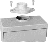 |
|
Rainproof Bolt-On Hubs |
Rainproof Bolt-On Hubs
All hubs are for indoor or rainproof applications.
Suitable for use with conduit having ANSI standard taper pipe thread.
Type 3R switches with catalog number ending in RB have a bolt-on closing cap factory installed:
-
Accepts 3/4 in. through 2-1/2 in. bolt-on hubs.
-
No gaskets required.
Type 3R switches with R suffix have blank top endwalls *
-
Accepts 3 in. through 4 in. bolt on hubs.
-
Gaskets provided.
-
Conduit entry holes must be cut in the field.
Rainproof Bolt-On Hubs *
| Conduit Size | 3/4 | 1 | 1-1/4 | 1-1/2 | 2 | 2-1/2 | 3 | 4 | Closing Cap |
|---|---|---|---|---|---|---|---|---|---|
| Hub Cat. No |
 |
|
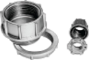
Water Resistant Hubs |
Water Resistant Hubs
-
Suitable for use with conduit having ANSI standard taper pipe thread.
-
Water resistant hubs are field installed on Type 4/4X/5 stainless steel and Type 12/3R and 12K enclosures.
-
Water resistant hubs are available in zinc or chrome plated finish.
-
Gaskets are provided.
Electrical Interlock Kits
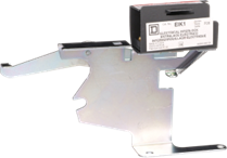 |
|
EIK1 Electrical Interlock Kit |
Electrical interlocks for heavy duty safety switches 30 A through 1200 A are available as field installed kits, or on Type 12 or Type 4X enclosure factory installed. A pivot arm operates from the switch mechanism, breaking the control circuit before the main switch blades break.
For factory installation catalog numbers available on Type 12 or 4X enclosures use the product configurator.
Electrical Interlock Kits * * *
| Switch Amperes Rating | Series Number* | Electrical Interlock Kit Cat. No.* |
|---|---|---|
|
30 |
F5–F8 |
|
|
60 (600 V) |
F5–F8 |
|
|
60 (240 V) |
F5–F8 |
|
|
100–200 |
F5–F8 |
|
|
30–100 Receptacle Switches |
F5–F7 |
|
|
30–200 4- and 6-Pole Switches |
F5–F6 |
|
|
400–1200 |
E4–E5 |
|
Electrical Interlock Contact Ratings *
| Interlock Type | AC 50 or 60 Hz | DC | |||||
|---|---|---|---|---|---|---|---|
| Volts | Make | Break | Cont. | Volts | Make / Break | Cont. | |
| 1 N. O. / 1 N. C. Contact (-1 Suffix *) |
120 |
40 A |
15 A |
15 A |
115 |
0.50 A |
15 A |
|
240 |
20 A |
10 A |
230 |
0.25 A |
|||
|
480 |
10 A |
6 A |
- |
- |
- |
||
|
600 |
8 A |
5 A |
600 |
0.05 A |
15 A |
||
| 2 N. O. / 2 N. C. Contacts (-2 Suffix *) |
120 |
30 A |
3 A |
10 A |
115 |
1.0 A |
10 A |
|
240 |
15 A |
1.5 A |
230 |
0.30 A |
|||
|
480 |
7.5 A |
0.75 A |
- |
- |
- |
||
|
600 |
6.0 A |
0.60 A |
600 |
0.10 A |
10 A |
||
Class R Fuse Kits
When installed, the kit limits switch to Class R fuses only. Kits are available for field installation. Each kit supports one three pole switch.
240 Vac–Class R Fuse Kits *
| Amperes | Series Number | Class R Fuse Kit Cat. No. |
|---|---|---|
|
30 |
F5–F6 |
|
|
60 |
||
|
100 |
||
|
200 |
||
|
400–600 |
E4–E5 |
|
Line Side Barrier Kits
Barrier kits protect against inadvertent contact with line side, uninsulated, ungrounded, or service terminal live parts.
Line Side Barrier Kits for Heavy Duty Safety Switch
| Amperes | Voltage | Blades/Fuses | Catalog |
|---|---|---|---|
|
30 |
600 |
2 or 3 |
|
|
30 / 60 |
240 |
2 or 3 |
|
|
60 |
600 |
2 or 3 |
|
|
100 |
240 / 600 |
2 or 3 |
|
|
200 |
240 |
3 |
|
|
3 |
|||
|
600 |
3 |
||
|
400 / 600 |
240 |
2 or 3 |
|
|
600 |
2 or 3 |
||
|
800 / 1200 |
240 |
2 |
|
|
3 |
|||
|
600 |
2 or 3 |
Internal Barrier Kits
SS06 |
Internal barrier kits provide an additional barrier that helps prevent accidental contact with live parts. Field-installed transparent barriers do not restrict visual inspection of the switch. Barrier provides IEC529 IP2X protection when door of enclosed disconnect switch is open. Designed with convenient door for accessing fuses for replacement without removing barrier and allows use of test probes.
Solid Neutral Assembly Kits
Solid Neutral Assembly Kits * * * *
| Amperes | Series Number | Standard Neutral Kit Cat. No. | Terminal Data AWG / kcmil | Optional Copper | Terminal Data AWG / kcmil |
|---|---|---|---|---|---|
| Only Neutral Kit Cat. No. | |||||
|
30 |
F5–F6 |
(2) 14-3 Al / Cu plus (1) 14-3 Al / Cu Svc Ground |
(2) 14-6 Cu plus (1) 14-6 Cu Svc Ground |
||
|
60 |
F5–F6 (240 V) |
(2) 14-3 Al / Cu plus (1) 14-3 Al / Cu Svc Ground |
(2) 14-6 Cu plus (1) 14-6 Cu Svc Ground |
||
|
F5–F6 (600 V) |
(2) 14-1/0 Al / Cu plus (2) 14-6 Al / Cu Svc Ground |
(2) 14-1/0 Cu plus (2) 14-6 Cu Svc Ground |
|||
|
100 |
F5–F6 |
(2) 14-1/0 Al / Cu plus (2) 14-6 Al / Cu Svc Ground |
(2) 14-1/0 Cu plus (2) 14-6 Cu Svc Ground |
||
|
200 * |
F5–F6 |
(2) 6-250 Al / Cu plus (1) 14-10 Al / Cu Svc Ground |
(2) 6-250 Cu plus (1) 14-1/0 Cu Svc Ground |
||
|
400 and 600 |
E4–E5 |
(4) 1-750 Al / Cu plus (1) 4-300 Al / Cu Svc Ground |
(2) 1-600 Cu and (2) 4-350 Cu plus (2) 6-250 Cu Svc Ground |
||
|
800 |
E4 |
(6) 3/0-750 Al / Cu plus (2) 6-350 Al / Cu Svc Ground |
– |
– |
|
|
1200 |
E4 |
(8) 3/0-750 Al / Cu plus (2) 6-350 Al / Cu Svc Ground |
|||
Fuse Puller Kits
 |
|
Fuse Puller Kits |
Fuse Puller Kits are standard equipment on the following 30–100 A switches: Type 12, Type 4/4X/5 stainless steel, Type 4X fiberglass reinforced polyester and Krydon.
Fuse Puller Kit available for field installation on Type 1 and Type 3R, 30–100 A switches. One Fuse Puller Kit required for a three-pole fusible 240 V or 600 V heavy duty switch. Fuse Puller Kits can be field installed on switches manufactured since February 1980.
Equipment Grounding Kits
Safety Switches with “GL” suffix come complete with factory installed Grounding Kits. Additional Grounding Kits are available for field or factory installation in 30–1200 A, 240 and 600 Volt Heavy Duty Switches.
Equipment Grounding Kits and Terminal Data * *
| Amperes | Series Number | Standard Cat. No. | Terminal Data AWG/kcmil | Optional Copper Only Cat. No. | Terminal Data AWG/kcmil |
|---|---|---|---|---|---|
|
30 |
F5–F6 |
(2) 14-4 Cu or (2) 12-4 Al |
(2) 14-6 Cu |
||
|
60 |
F5–F6 (600 V) |
(2) 14-1/0 Cu or (2) 12-1/0 Al |
(2) 14-1/0 Cu |
||
|
60 |
F5–F6 (240 V) |
(2) 14-4 Cu or (2) 12-4 Al |
(2) 14-6 Cu |
||
|
100 |
F5–F6 |
(2) 14-1/0 Cu or (2) 12-1/0 Al or |
(2) 14-1/0 Cu |
||
|
200 |
F5–F6 |
(2) 10-2/0 Cu |
(2) 14-4 Cu |
||
|
400 and 600 |
E4–E5 |
(2) 10-2/0 Cu |
(4) 14-1/0 Cu |
||
|
800 |
E4 |
(4) 4-350 Al / Cu |
– |
– |
|
|
1200 |
E4 |
(8) 4-350 Al / Cu |
– |
– |
|
Touch-Up Paint for Safety Switches
Cover Viewing Window–Heavy Duty Single Throw Switches
 |
Cover viewing window is positioned over the blades to allow visual verification of “ON” / “OFF” status.
-
Available as standard on Heavy Duty Single Throw Safety Switches 30, 60, 100, and 200 A , Type 1, Type 3R, Type 12, and Type 4X Stainless Steel Enclosures. * Except 4- and 6-pole switches.
-
Units can be obtained without window on Type 12 and Type 4X stainless steel devices–shipped from factory.
-
Available as factory modification on Type 12 and Type 4X enclosures–400, 600, 800, and 1200 A.
-
Viewing windows are not available on Type 7/9, 4X Fiberglass-reinforced Polyester Enclosures.
Lock OFF / Lock ON
 |
|
Optional Lock-OFF Guard Kit Installed |
Lock off provisions are standard on Heavy Duty Switches.
Lock-on is also available as a factory modification on Type 12 and 304 Stainless Steel Type 4X enclosures. Obtain by selecting on product configurator.
Modifying a switch in the field may be done to the 30–200 A, Series F switches, all NEMA enclosure types, and to 400–1200 A switches, Series E, all NEMA enclosure types. The lockplate on the side of the switch next to the handle has a very small indentation (a center punch) towards the top of the lockplate, which may be drilled out to accommodate a padlock. Note that drilling a hole in the steel of our painted devices will expose unpainted steel, which should be touched up with paint. Gray paint in a spray paint can be ordered, catalog number PK49SP.
Lock Off Guard Kits
For field installed kits, the lock off guard works by covering the lockout tagout openings whenever the switch is in the “ON” position. This protects against a padlock from being inadvertently inserted into the switch lockplate. Available ONLY for use on Type 1, Type 3R, Type 12, Heavy Duty Safety Switches. The lock off guard is designed to help prevent accidents caused by an untrained or distracted employee, who could inadvertently attempt to apply a lockout device to a switch without turning the switch to “OFF”. Lock-off guard kits can be installed on Square D 30–200 A F series Type 1, 3R, and 12 switches in less than 30 seconds. The bright red colour reminds users of the seriousness of lockout/tag-out procedures.
Key Interlock Systems
 |
|
Key Interlock System |
Interlocks help protect against unauthorized operation Factory installed only on heavy duty safety switches from 30 A to 1200 A, Type 12 and 304 stainless steel Type 4X. Not available on hazardous location devices (Type 7/9) or fiberglass reinforced polyester (Type 4X).
The key interlock system is a simple and easy method of applying individual key interlock units and assemblies to the above equipment so as to require operation in a predetermined sequence.
Quoting: Contact Schneider Electric for catalog number, availability, and pricing prior to quoting a job. Detailed information is required before an order can be processed.
Ordering: Order cannot be released for production until the following information has been provided:
-
End User–Company name, address.
-
Function of each lock (e.g., switch to be locked open with key removed, key held when switch is closed).
-
Existing Equipment–if switch is to be interlocked with equipment already on site, provide brand of existing lock and key number.
-
Other New Equipment–if switch is to be interlocked with new equipment not yet installed at the site, then provide contact person and phone number so that locks may be coordinated.
-
Additional information may be required upon order entry.
Use these suffixes on switch catalog numbers:
-
KI = 1 lock per switch
-
KI2 = 1 lock with 2 cylinders (2 keys) per switch
-
KIKI = 2 separate locks per switch
Voltage Monitors for Safety Switches
 |
|
Safety Switch with Voltage Monitoring |
Voltage monitors installed on safety switches indicate when voltage is present, helping to prevent hazards during maintenance work. Voltage monitors can be combined with other safety features such as Key Interlock, Viewing Windows or Lock-ON provisions.
-
Available on 30–1200 A Type 12 * and 4X–304 stainless-steel heavy-duty safety switches
-
Obtain by selecting on product configurator *
-
Not available on NEMA Type 7 and 9 and Type 4X Fiberglass and Krydon switches
|
Description |
|
|---|---|
|
Line side monitor |
SI |
|
Load side monitor |
LI |
|
Line and load side monitor |
LI2 |
Load Side Double Lug Kits
 |
|
AL20DTF |
200 A heavy duty F-Series switches are supplied standard with lugs suitable for one wire per phase. For two wires per phase and neutral, order the Double Lug Kit. Not included on switch wiring diagram as an accessory, available for Load Connections only. Lug can only be field installed on load side terminals. *
Copper Lug Kits
Lug kits that accept only copper wire are available for field installation:
-
Heavy Duty safety switches are supplied standard with Al lugs, which accept both Cu and Al wires.
-
Not available for use on Type 4X Fiberglass, Krydon or Type 7 and 9 switches.
-
For field installation, order copper lug kits. See Copper Lug Kits.
Compression Lug Kits–800 and 1200 A Safety Switches
 |
|
H12LKE2 |
-
Compression Lug Kits available for field installation
-
Compression Lug Kits contain VCEL07512H1 Versa-Crimp™ compression lugs
-
Order one Compression Lug Kit per switching pole and/or neutral (see Compression Lug Kits)
-
Example: Three-pole three-wire requires three kits; three-pole four-wire requires four kits.
Compression Lug Kits
| Amperes | Lug Kit Cat. No. | Conductors per phase | Lug Wire Range kcmil |
|---|---|---|---|
|
800 |
(3) Line and (3) Load |
500-750 kcmil (AI) |
|
|
1200 |
(4) Line and (4) Load |
500-750 kcmil (AI) |
Terminal Lug Data *
| Rating (A) | Wires Per Phase and Neutral | Lug Wire Range AWG / kcmil |
|---|---|---|
|
30 |
1 or 2 |
12–2 (Al) or 14–2 (Cu) |
|
60 * |
1 |
12–2 (Al) or 14–2 (Cu) |
|
100 * |
1 |
12–1/0 (Al) or 14–1/0 (Cu) |
|
200 * |
1 |
6–250 (Al / Cu) |
|
400 * |
1 or 2 |
1/0–750 (Al / Cu) or 1/0–300 (Al / Cu) |
|
600 |
2 |
3/0–500 (Al / Cu) |
|
800 |
3 |
3/0–750 (Al / Cu) |
|
1200 |
4 |
3/0–750 (Al / Cu) |
Conduit Provisions
Conduit Provisions *
| Amperes | Top and Bottom Endwall Type 4X Fiberglass Reinforced Polyester and Krydon |
|---|---|
|
30 |
3/4 in. |
|
60 |
1-1/4 in. |
|
100 |
2 in. |
|
200 |
2-1/2 in. |
Dimensions for Heavy Duty Safety Switches
VisiPacT Type 1 and 3R
See Terminal Lug Data for terminal lug data for the series switches listed in the dimension the Approximate Dimensions table.
Approximate Dimensions
|
Cat. No. |
Series |
H |
W |
D |
W/H |
Cat. No. |
Series |
H |
W |
D |
W/H |
||||||||
|---|---|---|---|---|---|---|---|---|---|---|---|---|---|---|---|---|---|---|---|
|
in. |
mm |
in. |
mm |
in. |
mm |
in. |
mm |
in. |
mm |
in. |
mm |
in. |
mm |
in. |
mm |
||||
|
F8 |
14.57 |
370 |
6.36 |
162 |
5.11 |
130 |
7.48 |
190 |
F8 |
14.84 |
377 |
6.63 |
168 |
5.05 |
128 |
7.6 |
193 |
||
|
F8 |
14.57 |
370 |
6.36 |
162 |
5.11 |
130 |
7.48 |
190 |
F8 |
14.84 |
377 |
6.63 |
168 |
5.05 |
128 |
7.6 |
193 |
||
|
F8 |
14.57 |
370 |
6.36 |
162 |
5.11 |
130 |
7.48 |
190 |
F8 |
14.84 |
377 |
6.63 |
168 |
5.05 |
128 |
7.6 |
193 |
||
|
F8 |
14.57 |
370 |
6.36 |
162 |
5.11 |
130 |
7.48 |
190 |
F8 |
14.84 |
377 |
6.63 |
168 |
5.05 |
128 |
7.6 |
193 |
||
|
F8 |
14.57 |
370 |
6.36 |
162 |
5.11 |
130 |
7.48 |
190 |
F8 |
14.84 |
377 |
6.63 |
168 |
5.05 |
128 |
7.6 |
193 |
||
|
F8 |
14.57 |
370 |
6.36 |
162 |
5.11 |
130 |
7.48 |
190 |
F8 |
14.84 |
377 |
6.63 |
168 |
5.05 |
128 |
7.6 |
193 |
||
|
F8 |
14.57 |
370 |
6.36 |
162 |
5.11 |
130 |
7.48 |
190 |
F8 |
14.84 |
377 |
6.63 |
168 |
5.05 |
128 |
7.6 |
193 |
||
|
F8 |
18.18 |
462 |
8.91 |
226 |
7.04 |
179 |
10.26 |
261 |
F8 |
18.4 |
467 |
9.08 |
231 |
6.98 |
177 |
10.39 |
264 |
||
|
F8 |
18.18 |
462 |
8.91 |
226 |
7.04 |
179 |
10.26 |
261 |
F8 |
18.4 |
467 |
9.08 |
231 |
6.98 |
177 |
10.39 |
264 |
||
|
F8 |
18.18 |
462 |
8.91 |
226 |
7.04 |
179 |
10.26 |
261 |
F8 |
18.4 |
467 |
9.08 |
231 |
6.98 |
177 |
10.39 |
264 |
||
|
F8 |
21.84 |
555 |
8.91 |
226 |
7.04 |
179 |
10.28 |
261 |
F8 |
22.1 |
561 |
9.08 |
231 |
7.02 |
178 |
10.42 |
265 |
||
|
F8 |
21.84 |
555 |
8.91 |
226 |
7.04 |
179 |
10.28 |
261 |
F8 |
22.1 |
561 |
9.08 |
231 |
7.02 |
178 |
10.42 |
265 |
||
|
F8 |
21.84 |
555 |
8.91 |
226 |
7.04 |
179 |
10.28 |
261 |
F8 |
22.1 |
561 |
9.08 |
231 |
7.02 |
178 |
10.42 |
265 |
||
|
F8 |
21.84 |
555 |
8.91 |
226 |
7.04 |
179 |
10.28 |
261 |
F8 |
22.1 |
561 |
9.08 |
231 |
7.02 |
178 |
10.42 |
265 |
||
|
F8 |
21.84 |
555 |
8.91 |
226 |
7.04 |
179 |
10.28 |
261 |
F8 |
22.1 |
561 |
9.08 |
231 |
7.02 |
178 |
10.42 |
265 |
||
|
F8 |
28 |
711 |
16.61 |
422 |
8.51 |
216 |
18.55 |
471 |
F8 |
28.94 |
735 |
17.02 |
432 |
8.51 |
216 |
18.36 |
466 |
||
|
F8 |
28 |
711 |
16.61 |
422 |
8.51 |
216 |
18.55 |
471 |
F8 |
28.94 |
735 |
17.02 |
432 |
8.51 |
216 |
18.36 |
466 |
||
|
F8 |
28 |
711 |
16.61 |
422 |
8.51 |
216 |
18.55 |
471 |
F8 |
28.94 |
735 |
17.02 |
432 |
8.51 |
216 |
18.36 |
466 |
||
|
F8 |
28 |
711 |
16.61 |
422 |
8.51 |
216 |
18.55 |
471 |
F8 |
28.94 |
735 |
17.02 |
432 |
8.51 |
216 |
18.36 |
466 |
||
|
F8 |
28 |
711 |
16.61 |
422 |
8.51 |
216 |
18.55 |
471 |
F8 |
28.94 |
735 |
17.02 |
432 |
8.51 |
216 |
18.36 |
466 |
||
VisiPacT Type 4X and 12
Approximate Dimensions
| Cat. No. | Series | H | W | D | W / H | Cat. No. | Series | H | W | D | W / H | ||||||||
|---|---|---|---|---|---|---|---|---|---|---|---|---|---|---|---|---|---|---|---|
| in. | mm | in. | mm | in. | mm | in. | mm | in. | mm | in. | mm | in. | mm | in. | mm | ||||
| F8 | 14.93 | 379 | 7.91 | 201 | 5.4 | 137 | 8.4 | 213 | F8 | 28.9 | 734 | 17.47 | 444 | 8.94 | 227 | 19.27 | 489 | ||
| F8 | 14.93 | 379 | 7.91 | 201 | 5.4 | 137 | 8.4 | 213 | F8 | 28.9 | 734 | 17.47 | 444 | 8.94 | 227 | 19.27 | 489 | ||
| F8 | 14.93 | 379 | 7.91 | 201 | 5.4 | 137 | 8.4 | 213 | F8 | 14.57 | 370 | 6.48 | 165 | 5.25 | 133 | 7.67 | 195 | ||
| F8 | 14.93 | 379 | 7.91 | 201 | 5.4 | 137 | 8.4 | 213 | F8 | 14.57 | 370 | 6.48 | 165 | 5.25 | 133 | 7.67 | 195 | ||
| F8 | 14.93 | 379 | 7.91 | 201 | 5.4 | 137 | 8.4 | 213 | F8 | 14.57 | 370 | 6.48 | 165 | 5.25 | 133 | 7.67 | 195 | ||
| F8 | 14.93 | 379 | 7.91 | 201 | 5.4 | 137 | 8.4 | 213 | F8 | 14.57 | 370 | 6.48 | 165 | 5.25 | 133 | 7.67 | 195 | ||
| F8 | 14.93 | 379 | 7.91 | 201 | 5.4 | 137 | 8.4 | 213 | F8 | 14.57 | 370 | 6.48 | 165 | 5.25 | 133 | 7.67 | 195 | ||
| F8 | 14.93 | 379 | 7.91 | 201 | 5.4 | 137 | 8.4 | 213 | F8 | 14.57 | 370 | 6.48 | 165 | 5.25 | 133 | 7.67 | 195 | ||
| F8 | 14.93 | 379 | 7.91 | 201 | 5.4 | 137 | 8.4 | 213 | F8 | 14.57 | 370 | 6.48 | 165 | 5.25 | 133 | 7.67 | 195 | ||
| F8 | 14.93 | 379 | 7.91 | 201 | 5.4 | 137 | 8.4 | 213 | F8 | 14.57 | 370 | 6.48 | 165 | 5.25 | 133 | 7.67 | 195 | ||
| F8 | 14.93 | 379 | 7.91 | 201 | 5.4 | 137 | 8.4 | 213 | F8 | 14.57 | 370 | 6.48 | 165 | 5.25 | 133 | 7.67 | 195 | ||
| F8 | 14.93 | 379 | 7.91 | 201 | 5.4 | 137 | 8.4 | 213 | F8 | 14.57 | 370 | 6.48 | 165 | 5.25 | 133 | 7.67 | 195 | ||
| F8 | 14.93 | 379 | 7.91 | 201 | 5.4 | 137 | 8.4 | 213 | F8 | 14.57 | 370 | 6.48 | 165 | 5.25 | 133 | 7.67 | 195 | ||
| F8 | 16.93 | 430 | 8.9 | 226 | 7.26 | 184 | 10.71 | 272 | F8 | 14.57 | 370 | 6.48 | 165 | 5.25 | 133 | 7.67 | 195 | ||
| F8 | 16.93 | 430 | 8.9 | 226 | 7.26 | 184 | 10.71 | 272 | F8 | 16.53 | 420 | 8.91 | 226 | 7.17 | 182 | 10.45 | 265 | ||
| F8 | 16.93 | 430 | 8.9 | 226 | 7.26 | 184 | 10.71 | 272 | F8 | 16.53 | 420 | 8.91 | 226 | 7.17 | 182 | 10.45 | 265 | ||
| F8 | 16.93 | 430 | 8.9 | 226 | 7.26 | 184 | 10.71 | 272 | F8 | 16.53 | 420 | 8.91 | 226 | 7.17 | 182 | 10.45 | 265 | ||
| F8 | 16.93 | 430 | 8.9 | 226 | 7.26 | 184 | 10.71 | 272 | F8 | 16.53 | 420 | 8.91 | 226 | 7.17 | 182 | 10.45 | 265 | ||
| F8 | 20.73 | 527 | 9.34 | 237 | 7.2 | 183 | 11.15 | 283 | F8 | 20.49 | 520 | 8.92 | 227 | 7.15 | 182 | 10.44 | 265 | ||
| F8 | 20.73 | 527 | 9.34 | 237 | 7.2 | 183 | 11.15 | 283 | F8 | 20.49 | 520 | 8.92 | 227 | 7.15 | 182 | 10.44 | 265 | ||
| F8 | 20.73 | 527 | 9.34 | 237 | 7.2 | 183 | 11.15 | 283 | F8 | 20.49 | 520 | 8.92 | 227 | 7.15 | 182 | 10.44 | 265 | ||
| F8 | 20.73 | 527 | 9.34 | 237 | 7.2 | 183 | 11.15 | 283 | F8 | 20.49 | 520 | 8.92 | 227 | 7.15 | 182 | 10.44 | 265 | ||
| F8 | 20.73 | 527 | 9.34 | 237 | 7.2 | 183 | 11.15 | 283 | F8 | 20.49 | 520 | 8.92 | 227 | 7.15 | 182 | 10.44 | 265 | ||
| F8 | 20.73 | 527 | 9.34 | 237 | 7.2 | 183 | 11.15 | 283 | F8 | 20.49 | 520 | 8.92 | 227 | 7.15 | 182 | 10.44 | 265 | ||
| F8 | 20.73 | 527 | 9.34 | 237 | 7.2 | 183 | 11.15 | 283 | F8 | 20.49 | 520 | 8.92 | 227 | 7.15 | 182 | 10.44 | 265 | ||
| F8 | 20.73 | 527 | 9.34 | 237 | 7.2 | 183 | 11.15 | 283 | F8 | 20.49 | 520 | 8.92 | 227 | 7.15 | 182 | 10.44 | 265 | ||
| F8 | 20.73 | 527 | 9.34 | 237 | 7.2 | 183 | 11.15 | 283 | F8 | 28.93 | 735 | 17.01 | 432 | 9.02 | 229 | 18.58 | 472 | ||
| F8 | 28.9 | 734 | 17.47 | 444 | 8.94 | 227 | 19.27 | 489 | F8 | 28.93 | 735 | 17.01 | 432 | 9.02 | 229 | 18.58 | 472 | ||
| F8 | 28.9 | 734 | 17.47 | 444 | 8.94 | 227 | 19.27 | 489 | F8 | 28.93 | 735 | 17.01 | 432 | 9.02 | 229 | 18.58 | 472 | ||
| F8 | 28.9 | 734 | 17.47 | 444 | 8.94 | 227 | 19.27 | 489 | F8 | 28.93 | 735 | 17.01 | 432 | 9.02 | 229 | 18.58 | 472 | ||
| F8 | 28.9 | 734 | 17.47 | 444 | 8.94 | 227 | 19.27 | 489 | F8 | 28.93 | 735 | 17.01 | 432 | 9.02 | 229 | 18.58 | 472 | ||
| F8 | 28.9 | 734 | 17.47 | 444 | 8.94 | 227 | 19.27 | 489 | F8 | 28.93 | 735 | 17.01 | 432 | 9.02 | 229 | 18.58 | 472 | ||
| F8 | 28.9 | 734 | 17.47 | 444 | 8.94 | 227 | 19.27 | 489 | F8 | 28.93 | 735 | 17.01 | 432 | 9.02 | 229 | 18.58 | 472 | ||
| F8 | 28.9 | 734 | 17.47 | 444 | 8.94 | 227 | 19.27 | 489 | F8 | 28.93 | 735 | 17.01 | 432 | 9.02 | 229 | 18.58 | 472 | ||
Type 1 and 3R
Approximate Dimensions
| Cat. No. | Series | H | W | D | W/H | Cat. No. | Series | H | W | D | W/H | ||||||||
|---|---|---|---|---|---|---|---|---|---|---|---|---|---|---|---|---|---|---|---|
| in. | mm | in. | mm | in. | mm | in. | mm | in. | mm | in. | mm | in. | mm | in. | mm | ||||
| E4 | 50.25 | 1276 | 27.63 | 702 | 10.13 | 257 | 27.63 | 702 | E4 | 69.13 | 1756 | 36.62 | 930 | 17.75 | 451 | 36.62 | 930 | ||
| E4 | 50.25 | 1276 | 27.63 | 702 | 10.13 | 257 | 27.63 | 702 | E4 | 50.25 | 1276 | 27.63 | 702 | 10.13 | 257 | 27.63 | 702 | ||
| E5 | 50.31 | 1278 | 27.76 | 705 | 9.53 | 242 | 27.88 | 708 | E4 | 50.25 | 1276 | 27.63 | 702 | 10.13 | 257 | 27.63 | 702 | ||
| E5 | 50.31 | 1278 | 27.76 | 705 | 9.53 | 242 | 27.88 | 708 | E5 | 50.31 | 1278 | 27.76 | 705 | 9.53 | 242 | 27.88 | 708 | ||
| E4 | 50.25 | 1276 | 27.63 | 702 | 10.13 | 257 | 27.63 | 702 | E5 | 50.31 | 1278 | 27.76 | 705 | 9.53 | 242 | 27.88 | 708 | ||
| E4 | 50.25 | 1276 | 27.63 | 702 | 10.13 | 257 | 27.63 | 702 | E4 | 50.25 | 1276 | 27.63 | 702 | 10.13 | 257 | 27.63 | 702 | ||
| E5 | 50.31 | 1278 | 27.76 | 705 | 9.53 | 242 | 27.88 | 708 | E4 | 50.25 | 1276 | 27.63 | 702 | 10.13 | 257 | 27.63 | 702 | ||
| E5 | 50.31 | 1278 | 27.76 | 705 | 9.53 | 242 | 27.88 | 708 | E5 | 50.31 | 1278 | 27.76 | 705 | 9.53 | 242 | 27.88 | 708 | ||
| E4 | 69.13 | 1756 | 36.62 | 930 | 17.75 | 451 | 36.62 | 930 | E5 | 50.31 | 1278 | 27.76 | 705 | 9.53 | 242 | 27.88 | 708 | ||
| E4 | 69.13 | 1756 | 36.62 | 930 | 17.75 | 451 | 36.62 | 930 | E4 | 69.13 | 1756 | 36.62 | 930 | 17.75 | 451 | 36.62 | 930 | ||
| E4 | 69.13 | 1756 | 36.62 | 930 | 17.75 | 451 | 36.62 | 930 | E4 | 69.13 | 1756 | 36.62 | 930 | 17.75 | 451 | 36.62 | 930 | ||
| E4 | 69.13 | 1756 | 36.62 | 930 | 17.75 | 451 | 36.62 | 930 | E4 | 69.13 | 1756 | 36.62 | 930 | 17.75 | 451 | 36.62 | 930 | ||
| E4 | 69.13 | 1756 | 36.62 | 930 | 17.75 | 451 | 36.62 | 930 | E4 | 69.13 | 1756 | 36.62 | 930 | 17.75 | 451 | 36.62 | 930 | ||
| E4 | 69.13 | 1756 | 36.62 | 930 | 17.75 | 451 | 36.62 | 930 | E4 | 69.13 | 1756 | 36.62 | 930 | 17.75 | 451 | 36.62 | 930 | ||
| E4 | 69.13 | 1756 | 36.62 | 930 | 17.75 | 451 | 36.62 | 930 | E4 | 69.13 | 1756 | 36.62 | 930 | 17.75 | 451 | 36.62 | 930 | ||
| E4 | 69.13 | 1756 | 36.62 | 930 | 17.75 | 451 | 36.62 | 930 | E4 | 69.13 | 1756 | 36.62 | 930 | 17.75 | 451 | 36.62 | 930 | ||
| E4 | 50.25 | 1276 | 27.63 | 702 | 10.13 | 257 | 27.63 | 702 | E4 | 69.13 | 1756 | 36.62 | 930 | 17.75 | 451 | 36.62 | 930 | ||
| E5 | 50.31 | 1278 | 27.76 | 705 | 9.53 | 242 | 27.88 | 708 | E4 | 50.25 | 1276 | 27.63 | 702 | 10.13 | 257 | 27.63 | 702 | ||
| E4 | 50.25 | 1276 | 27.63 | 702 | 10.13 | 257 | 27.63 | 702 | E5 | 50.31 | 1278 | 27.76 | 705 | 9.53 | 242 | 27.88 | 708 | ||
| E5 | 50.31 | 1278 | 27.76 | 705 | 9.53 | 242 | 27.88 | 708 | E4 | 50.25 | 1276 | 27.63 | 702 | 10.13 | 257 | 27.63 | 702 | ||
| E4 | 69.13 | 1756 | 36.62 | 930 | 17.75 | 451 | 36.62 | 930 | E5 | 50.31 | 1278 | 27.76 | 705 | 9.53 | 242 | 27.88 | 708 | ||
| E4 | 69.13 | 1756 | 36.62 | 930 | 17.75 | 451 | 36.62 | 930 | E4 | 69.13 | 1756 | 36.62 | 930 | 17.75 | 451 | 36.62 | 930 | ||
| E4 | 69.13 | 1756 | 36.62 | 930 | 17.75 | 451 | 36.62 | 930 | E4 | 69.13 | 1756 | 36.62 | 930 | 17.75 | 451 | 36.62 | 930 | ||
| E4 | 69.13 | 1756 | 36.62 | 930 | 17.75 | 451 | 36.62 | 930 | E4 | 69.13 | 1756 | 36.62 | 930 | 17.75 | 451 | 36.62 | 930 | ||
| E4 | 50.25 | 1276 | 27.88 | 708 | 10.13 | 257 | 27.88 | 708 | E4 | 69.13 | 1756 | 36.62 | 930 | 17.75 | 451 | 36.62 | 930 | ||
| E4 | 50.25 | 1276 | 27.88 | 708 | 10.13 | 257 | 27.88 | 708 | E4 | 50.25 | 1276 | 27.63 | 702 | 10.13 | 257 | 27.63 | 702 | ||
| E5 | 50.31 | 1278 | 27.76 | 705 | 9.53 | 242 | 27.88 | 708 | E5 | 50.31 | 1278 | 27.76 | 705 | 9.53 | 242 | 27.88 | 708 | ||
| E5 | 50.31 | 1278 | 27.76 | 705 | 9.53 | 242 | 27.88 | 708 | E4 | 50.25 | 1276 | 27.63 | 702 | 10.13 | 257 | 27.63 | 702 | ||
| E4 | 50.25 | 1276 | 27.63 | 702 | 10.13 | 257 | 27.63 | 702 | E5 | 50.31 | 1278 | 27.76 | 705 | 9.53 | 242 | 27.88 | 708 | ||
| E4 | 50.25 | 1276 | 27.63 | 702 | 10.13 | 257 | 27.63 | 702 | E4 | 69.13 | 1756 | 36.62 | 930 | 17.75 | 451 | 36.62 | 930 | ||
| E5 | 50.31 | 1278 | 27.76 | 705 | 9.53 | 242 | 27.88 | 708 | E4 | 69.13 | 1756 | 36.62 | 930 | 17.75 | 451 | 36.62 | 930 | ||
| E5 | 50.31 | 1278 | 27.76 | 705 | 9.53 | 242 | 27.88 | 708 | E4 | 69.13 | 1756 | 36.62 | 930 | 17.75 | 451 | 36.62 | 930 | ||
| E4 | 69.13 | 1756 | 36.62 | 930 | 17.75 | 451 | 36.62 | 930 | E4 | 69.13 | 1756 | 36.62 | 930 | 17.75 | 451 | 36.62 | 930 | ||
| E4 | 69.13 | 1756 | 36.62 | 930 | 17.75 | 451 | 36.62 | 930 | F5 | 20.5 | 521 | 14.75 | 375 | 6.85 | 174 | 16.13 | 410 | ||
| E4 | 69.13 | 1756 | 36.62 | 930 | 17.75 | 451 | 36.62 | 930 | F5 | 20.5 | 521 | 14.75 | 375 | 6.85 | 174 | 16.13 | 410 | ||
| E4 | 69.13 | 1756 | 36.62 | 930 | 17.75 | 451 | 36.62 | 930 | F5 | 20.5 | 521 | 14.75 | 375 | 6.85 | 174 | 16.13 | 410 | ||
| E4 | 69.13 | 1756 | 36.62 | 930 | 17.75 | 451 | 36.62 | 930 | F5 | 29 | 737 | 23.25 | 591 | 8.75 | 222 | 24.88 | 632 | ||
| E4 | 69.13 | 1756 | 36.62 | 930 | 17.75 | 451 | 36.62 | 930 | E4 | 50.25 | 1276 | 33.88 | 861 | 10.13 | 257 | 33.88 | 861 | ||
| E4 | 69.13 | 1756 | 36.62 | 930 | 17.75 | 451 | 36.62 | 930 | E4 | 50.25 | 1276 | 33.88 | 861 | 10.13 | 257 | 33.88 | 861 | ||
Type 4, 4X, 5, 12, NEMA Type 7 and 9
See Terminal Lug Data, for terminal lug data for the series switches listed in the following table.
Approximate Dimensions
| Cat. No. | Series | H | W | D | W/H | Cat. No. | Series | H | W | D | W/H | ||||||||
|---|---|---|---|---|---|---|---|---|---|---|---|---|---|---|---|---|---|---|---|
| in. | mm | in. | mm | in. | mm | in. | mm | in. | mm | in. | mm | in. | mm | in. | mm | ||||
| E4 | 46.25 | 1175 | 26.25 | 667 | 10.13 | 259 | 26.25 | 667 | F6 | 20.5 | 521 | 14.75 | 375 | 6.8 | 173 | 16.13 | 410 | ||
| E4 | 46.25 | 1175 | 26.25 | 667 | 10.13 | 259 | 26.25 | 667 | F6 | 20.82 | 529 | 15.08 | 383 | 6.97 | 177 | 16.85 | 428 | ||
| E4 | 46.25 | 1175 | 26.25 | 667 | 10.13 | 259 | 26.25 | 667 | F6 | 20.5 | 521 | 14.75 | 375 | 6.8 | 173 | 16.13 | 410 | ||
| A1 | 22.56 | 573 | 10.88 | 276 | 7.75 | 197 | 10.88 | 276 | F6 | 20.82 | 529 | 15.08 | 383 | 6.97 | 177 | 16.85 | 428 | ||
| E5 | 46.25 | 1175 | 26.25 | 667 | 10.13 | 259 | 26.25 | 667 | F6 | 20.5 | 521 | 14.75 | 375 | 6.8 | 173 | 16.13 | 410 | ||
| E5 | 46.25 | 1175 | 26.25 | 667 | 10.13 | 259 | 26.25 | 667 | F6 | 20.82 | 529 | 15.08 | 383 | 6.97 | 177 | 16.85 | 428 | ||
| E5 | 46.25 | 1175 | 26.25 | 667 | 10.13 | 259 | 26.25 | 667 | F6 | 29 | 737 | 23.25 | 591 | 8.75 | 222 | 24.88 | 632 | ||
| E5 | 46.25 | 1175 | 26.25 | 667 | 10.13 | 259 | 26.25 | 667 | F6 | 29 | 737 | 23.75 | 603 | 8.88 | 226 | 25.25 | 641 | ||
| E4 | 69.13 | 1756 | 36.62 | 930 | 17.75 | 451 | 36.62 | 930 | E5 | 46.25 | 1175 | 32.5 | 826 | 10.13 | 259 | 32.5 | 826 | ||
| E4 | 69.13 | 1756 | 36.62 | 930 | 17.75 | 451 | 36.62 | 930 | F6 | 20.5 | 521 | 14.75 | 375 | 6.8 | 173 | 16.13 | 410 | ||
| E4 | 69.13 | 1756 | 36.62 | 930 | 17.75 | 451 | 36.62 | 930 | F6 | 20.82 | 529 | 15.08 | 383 | 6.97 | 177 | 16.85 | 428 | ||
| E4 | 69.13 | 1756 | 36.62 | 930 | 17.75 | 451 | 36.62 | 930 | F6 | 29 | 737 | 23.25 | 591 | 8.75 | 222 | 24.88 | 632 | ||
| E5 | 46.25 | 1175 | 26.25 | 667 | 10.13 | 259 | 26.25 | 667 | F6 | 29 | 737 | 23.75 | 603 | 8.88 | 226 | 25.25 | 641 | ||
| E5 | 46.25 | 1175 | 26.25 | 667 | 10.13 | 259 | 26.25 | 667 | E5 | 46.25 | 1175 | 26.25 | 667 | 10.13 | 259 | 26.25 | 667 | ||
| E5 | 46.25 | 1175 | 26.25 | 667 | 10.13 | 259 | 26.25 | 667 | E5 | 46.25 | 1175 | 26.25 | 667 | 10.13 | 259 | 26.25 | 667 | ||
| E5 | 46.25 | 1175 | 26.25 | 667 | 10.13 | 259 | 26.25 | 667 | E5 | 46.25 | 1175 | 26.25 | 667 | 10.13 | 259 | 26.25 | 667 | ||
| E5 | 46.25 | 1175 | 26.25 | 667 | 10.13 | 259 | 26.25 | 667 | E5 | 46.25 | 1175 | 26.25 | 667 | 10.13 | 259 | 26.25 | 667 | ||
| E4 | 69.13 | 1756 | 36.62 | 930 | 17.75 | 451 | 36.62 | 930 | E4 | 69.13 | 1756 | 36.62 | 930 | 17.75 | 451 | 36.62 | 930 | ||
| E4 | 69.13 | 1756 | 36.62 | 930 | 17.75 | 451 | 36.62 | 930 | E4 | 69.13 | 1756 | 36.62 | 930 | 17.75 | 451 | 36.62 | 930 | ||
| E4 | 69.13 | 1756 | 36.62 | 930 | 17.75 | 451 | 36.62 | 930 | F1 | 16.5 | 419 | 11 | 279 | 8.8 | 224 | 11 | 279 | ||
| E4 | 69.13 | 1756 | 36.62 | 930 | 17.75 | 451 | 36.62 | 930 | F1 | 19.4 | 493 | 11.4 | 290 | 8.6 | 218 | 11.4 | 290 | ||
| E5 | 46.25 | 1175 | 26.25 | 667 | 10.13 | 259 | 26.25 | 667 | F1 | 16.5 | 419 | 11 | 279 | 8.8 | 224 | 11 | 279 | ||
| E5 | 46.25 | 1175 | 26.25 | 667 | 10.13 | 259 | 26.25 | 667 | F1 | 19.4 | 493 | 11.4 | 290 | 8.6 | 218 | 11.4 | 290 | ||
| E5 | 46.25 | 1175 | 26.25 | 667 | 10.13 | 259 | 26.25 | 667 | F1 | 24.8 | 630 | 13.7 | 348 | 12 | 305 | 13.7 | 348 | ||
| E5 | 46.25 | 1175 | 26.25 | 667 | 10.13 | 259 | 26.25 | 667 | F1 | 25.25 | 641 | 11.4 | 290 | 8.6 | 218 | 11.4 | 290 | ||
| E5 | 46.25 | 1175 | 26.25 | 667 | 10.13 | 259 | 26.25 | 667 | E1 | 31.3 | 795 | 26.3 | 668 | 11.8 | 300 | 26.3 | 668 | ||
| E4 | 69.13 | 1756 | 36.62 | 930 | 17.75 | 451 | 36.62 | 930 | E5 | 46.25 | 1175 | 26.25 | 667 | 10.13 | 259 | 26.25 | 667 | ||
| E4 | 69.13 | 1756 | 36.62 | 930 | 17.75 | 451 | 36.62 | 930 | E5 | 46.25 | 1175 | 26.25 | 667 | 10.13 | 259 | 26.25 | 667 | ||
| E4 | 69.13 | 1756 | 36.62 | 930 | 17.75 | 451 | 36.62 | 930 | E5 | 46.25 | 1175 | 26.25 | 667 | 10.13 | 259 | 26.25 | 667 | ||
| E4 | 69.13 | 1756 | 36.62 | 930 | 17.75 | 451 | 36.62 | 930 | E5 | 46.25 | 1175 | 26.25 | 667 | 10.13 | 259 | 26.25 | 667 | ||
| F1 | 16.5 | 419 | 11 | 279 | 8.8 | 224 | 11 | 279 | E5 | 46.25 | 1175 | 26.25 | 667 | 10.13 | 259 | 26.25 | 667 | ||
| F1 | 19.4 | 493 | 11.4 | 290 | 8.6 | 218 | 11.4 | 290 | E5 | 46.25 | 1175 | 26.25 | 667 | 10.13 | 259 | 26.25 | 667 | ||
| F1 | 16.5 | 419 | 11 | 279 | 8.8 | 224 | 11 | 279 | E4 | 69.13 | 1756 | 36.62 | 930 | 17.75 | 451 | 36.62 | 930 | ||
| F1 | 19.4 | 493 | 11.4 | 290 | 8.6 | 218 | 11.4 | 290 | E4 | 69.13 | 1756 | 36.62 | 930 | 17.75 | 451 | 36.62 | 930 | ||
| F1 | 24.8 | 630 | 13.7 | 348 | 12 | 305 | 13.7 | 348 | F6 | 20.5 | 521 | 14.75 | 375 | 6.8 | 173 | 16.13 | 411 | ||
| F1 | 25.25 | 641 | 11.4 | 290 | 8.6 | 218 | 11.4 | 290 | F6 | 20.82 | 529 | 15.08 | 383 | 6.97 | 177 | 16.85 | 428 | ||
| E5 | 46.25 | 1175 | 26.25 | 667 | 10.13 | 259 | 26.25 | 667 | F6 | 21.25 | 540 | 16.13 | 410 | 6.8 | 173 | 16.13 | 410 | ||
| E1 | 31.3 | 795 | 26.3 | 668 | 11.8 | 300 | 26.3 | 668 | F6 | 20.82 | 529 | 15.08 | 383 | 6.97 | 177 | 16.85 | 428 | ||
| E5 | 46.25 | 1175 | 26.25 | 667 | 10.13 | 259 | 26.25 | 667 | F6 | 20.5 | 521 | 14.75 | 375 | 6.8 | 173 | 16.13 | 410 | ||
| E5 | 46.25 | 1175 | 26.25 | 667 | 10.13 | 259 | 26.25 | 667 | F6 | 20.82 | 529 | 15.08 | 383 | 6.97 | 177 | 16.85 | 428 | ||
| E5 | 46.25 | 1175 | 26.25 | 667 | 10.13 | 259 | 26.25 | 667 | F6 | 29 | 737 | 23.25 | 591 | 8.75 | 222 | 24.88 | 632 | ||
| E5 | 46.25 | 1175 | 26.25 | 667 | 10.13 | 259 | 26.25 | 667 | F6 | 29 | 737 | 23.75 | 603 | 8.88 | 226 | 25.25 | 641 | ||
| E5 | 46.25 | 1175 | 26.25 | 667 | 10.13 | 259 | 26.25 | 667 | E5 | 46.25 | 1175 | 32.5 | 826 | 10.13 | 259 | 32.5 | 826 | ||
| E5 | 46.25 | 1175 | 26.25 | 667 | 10.13 | 259 | 26.25 | 667 | F6 | 20.5 | 521 | 14.75 | 375 | 6.8 | 173 | 16.13 | 410 | ||
| E5 | 46.25 | 1175 | 26.25 | 667 | 10.13 | 259 | 26.25 | 667 | F6 | 20.82 | 529 | 15.08 | 383 | 6.97 | 177 | 16.85 | 428 | ||
| E5 | 46.25 | 1175 | 26.25 | 667 | 10.13 | 259 | 26.25 | 667 | F6 | 20.5 | 521 | 14.75 | 375 | 6.8 | 173 | 16.13 | 410 | ||
| E5 | 46.25 | 1175 | 26.25 | 667 | 10.13 | 259 | 26.25 | 667 | F6 | 20.82 | 529 | 15.08 | 383 | 6.97 | 177 | 16.85 | 428 | ||
| E4 | 69.13 | 1756 | 36.62 | 930 | 17.75 | 451 | 36.62 | 930 | F6 | 20.5 | 521 | 14.75 | 375 | 6.8 | 173 | 16.13 | 410 | ||
| E4 | 69.13 | 1756 | 36.62 | 930 | 17.75 | 451 | 36.62 | 930 | F6 | 20.82 | 529 | 15.08 | 383 | 6.97 | 177 | 16.85 | 428 | ||
| E4 | 69.13 | 1756 | 36.62 | 930 | 17.75 | 451 | 36.62 | 930 | F6 | 29 | 737 | 23.25 | 591 | 8.75 | 222 | 24.88 | 632 | ||
| E4 | 69.13 | 1756 | 36.62 | 930 | 17.75 | 451 | 36.62 | 930 | F6 | 29 | 737 | 23.75 | 603 | 8.88 | 226 | 25.25 | 641 | ||