
View Fiber Connections
When Connection Manager opens initially, it displays the two fiber facilities that appear alphabetically first at that location. From that point forward, you have control over the display and what connections you wish to view.
Connection Drop-Down
Use the drop-downs on either side of the dialog to choose which fiber facilities you want to view.

Once you choose a fiber facility, the display automatically updates to show those fibers or ports and their connections.
Map Color
Connection Manager displays the fiber facilities currently in the connection view by highlighting them on the map.
You can change the highlight colors using the color drop-downs. This is particularly helpful if the default color happens to be similar to an existing color in your Stored Display.

Connection Display
The main part of the Connection Manager dialog is devoted to showing the connections among fibers and ports.

The dialog uses various symbols to indicate connection information:
-
A black line indicates a connection between the two records currently visible.
-
When viewing a splice, the tray number is displayed as well.
-
-
A scarlet line indicates a connection that is currently visible and also part of a circuit.
-
Hovering over a circuit connection displays the circuit names in the lower, left-hand corner, as seen in the image above.
-
-
A stub
 icon indicates the fiber or port is currently not connected
to anything.
icon indicates the fiber or port is currently not connected
to anything. -
A “squap”
 icon indicates the fiber or port is connected, but not to the fiber feature on the opposite side of
Connection Manager.
icon indicates the fiber or port is connected, but not to the fiber feature on the opposite side of
Connection Manager.-
Hover over the squap to display the other side of the connection that is currently not visible.
-
Right-click the squap and choose Show Both Sides of Connection to change the opposite side of Connection Manager to show the connected feature.
 TIP: When viewing hundreds of connections that are densely packed in the dialog, use the Show Both Sides of Connection to quickly “clean up” the display. It moves the connection you right-click to the top of the dialog, making its connection line straight and easy to see. For example, in the following image it is difficult to discern the individual connection among the hundreds. After using the Show Both Sides of Connection command, the connection of interest is moved to the top of the display.
-
Connection Filters
When viewing cables or patch locations with hundreds (or even thousands) of connections, adding a filter reduces the number of visible connections and helps you find relevant connections faster. For example, in the following image, part of a circuit name was typed, and Connection Manager automatically reduced the visible connections to only show those fibers that had a part of that name.

When using a filter, keep the following in mind:
-
Filters are instantaneous. The dialog immediately starts filtering as you type, and there is no Apply button.
-
By default, the filter queries all columns in Connection Manager, except color columns. You can also use the drop-down to specify the column to query.

-
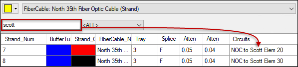
The filter field acts like a keyword-style search. In other words, it searches anywhere within the attribute fields. In the following image, notice the word “scott” was typed, and two results with the word “scott” in the middle of the circuit name were returned.
-
Invalid filter entries turn the field red, and the Connection Manager display is not filtered. In the following image, the word “circuit” was typed, but the query column was set to Strand_Num. Strand_Num is a numeric field, so this filter is invalid.

-
Regarding numeric fields, there are two ways to filter:
-
Type a single number. In the following image, 112 was typed to filter the strands, and only that strand is displayed.

-
Type a range of numbers surrounded by square brackets. In the following image, the filter [22–26] was typed to filter back ports, and only those ports are displayed.

This is a great way to jump to a section within a high-volume cable or a patch panel with hundreds of ports.
IMPORTANT: The numeric range filter works with any numeric field, unless the field is associated to a domain (which is a list of pre-defined values). For example, if your tray numbers come from a domain, the range filter does not work with them even though they are numeric. You can still type a single number to filter a domain-associated, numeric field.
-
-
A filter might prevent a connection from being visible on both sides of the display. In this case, a filtered connection
 icon appears. In the following image, a Strand_Num filter of [112–116]
was applied on the right side of Connection Manager. On the left side,
notice there are several filtered connection icons.
icon appears. In the following image, a Strand_Num filter of [112–116]
was applied on the right side of Connection Manager. On the left side,
notice there are several filtered connection icons.
This means that these fibers are connected to the opposite cable, but the filter is currently preventing those connections from being visible. This is different than the squap
icon, which
indicates the fiber is connected, but not to the fiber feature
on the opposite side of Connection Manager.-
Hover over the icon to see what the connection is on the opposite side. As seen in the image above, the fiber is connected to strand 117, but strand 117 is currently filtered out.
-
You cannot right-click and Show Both Sides of Connection in this scenario. This is because the dialog defers to keeping the filter in place rather than changing the display. Clear the filter if you need to see both sides.
-
-
When a device has the model name SUPPORTSSELFCONNECTION (commonly done with patch panels so you can add jumpers to multiple front side ports), and you choose to see the same device on both sides of Connection Manager, the filter on the right side automatically disables. This is because you are viewing the same device, so there is no need to have two separate filters.
You can still use the filter on the left side, and both sides of Connection Manager respect the filter. In the following image, a front port filter [5–6] has been added, and both sides are now showing only those two ports. Adding this kind of filter would make it easier to then add the jumper connecting port 5 to port 6 on the front side.

Hide Unavailable Items
As a quick way to reduce the number of possible connections, check the box to Hide unavailable items. This is particularly helpful when searching for available fibers for either new service or a new circuit.

For example, notice in the following image that several connections have existing circuits. Circuits are commonly attributed as unavailable.

With the Hide unavailable items checked, those circuits are removed from the display.

The check box hides unavailable items on both sides of Connection Manager.