
Connect the Signal Cables
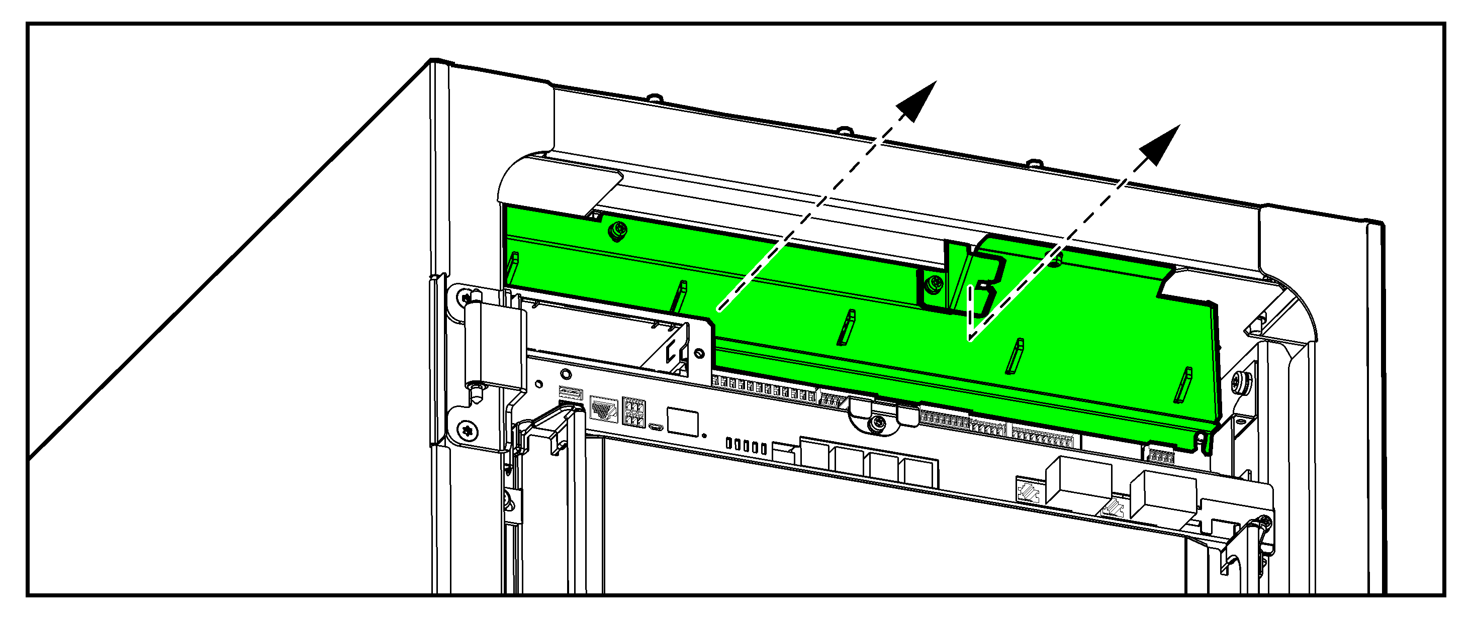
Front View of the UPS – Board 640-4843 and 640-4864

- Remove the top gland plates and the top brush plates from the UPS. These are for signal
cable routing.

- Perform one of the following:
- For installation without conduits: Reinstall the brush plates.
- For installation with conduits: Drill a hole in the gland plates for conduits, install conduits, and reinstall the gland plates.
- Remove the indicated covers.
- Route the non-Class 2/non-SELV signal cables through the right brush/gland plate.
- Route the Class 2/SELV signal cables through the left and middle brush/gland plate.
UPS without Conduits

UPS with Conduits

- Connect the Class 2/SELV signal cables from the auxiliary products to board 640-4864 in the UPS. Follow the instructions in the auxiliary product manuals.
- Connect the Class 2/SELV signal cables to the input contacts and output relays on board 640-4864 in the UPS.
Do not connect any circuit to the input contacts unless it can be confirmed that the circuit is Class 2/SELV.
Four input contacts are available. Three input contacts can be configured to indicate a given event via the display. The input contacts support 24 VDC 10 mA. All circuits connected must have the same 0 V reference.

Name Description Location Alarm text on UPS display IN _1 (input contact 1) Preconfigured input contact (reserved for input isolation transformer overtemperature) 640-4864 terminal J6616, 1-2 Transformer temperature is too high IN _2 (input contact 2) Configurable input contact 640-4864 terminal J6616, 3-4 IN _3 (input contact 3) Configurable input contact 640-4864 terminal J6616, 5-6 IN _4 (input contact 4) Configurable input contact 640-4864 terminal J6616, 7-8 The output relays are preconfigured for use with the remote alarm panel GVSOPT036. If the remote alarm panel is not part of the installation, the output relays can be reconfigured for other functions – see the operation manual. The output relays support 24 VAC/VDC 1 A. All external circuitry must be fused with maximum 1 A fast acting fuses.

Name Description Location Alarm text on UPS display Corresponding lamp on remote alarm panel OUT _1 (output relay 1) Preconfigured output relay 640-4864 terminal J6617, 1-3 UPS in normal operation UPS ONLINE OUT _2 (output relay 2) Preconfigured output relay 640-4864 terminal J6617, 4-6 UPS common alarm UPS General Alarm OUT _3 (output relay 3) Preconfigured output relay 640-4864 terminal J6617, 7-9 UPS in battery operation UPS on Battery OUT _4 (output relay 4) Preconfigured output relay 640-4864 terminal J6617, 10-12 Battery voltage low UPS Low Battery - Connect the non-Class 2/non-SELV signal cables from the auxiliary products to board 640-4843 in the UPS. Follow the instructions in the auxiliary product manuals.
