
Auxiliary Cradle
Auxiliary cradle overview
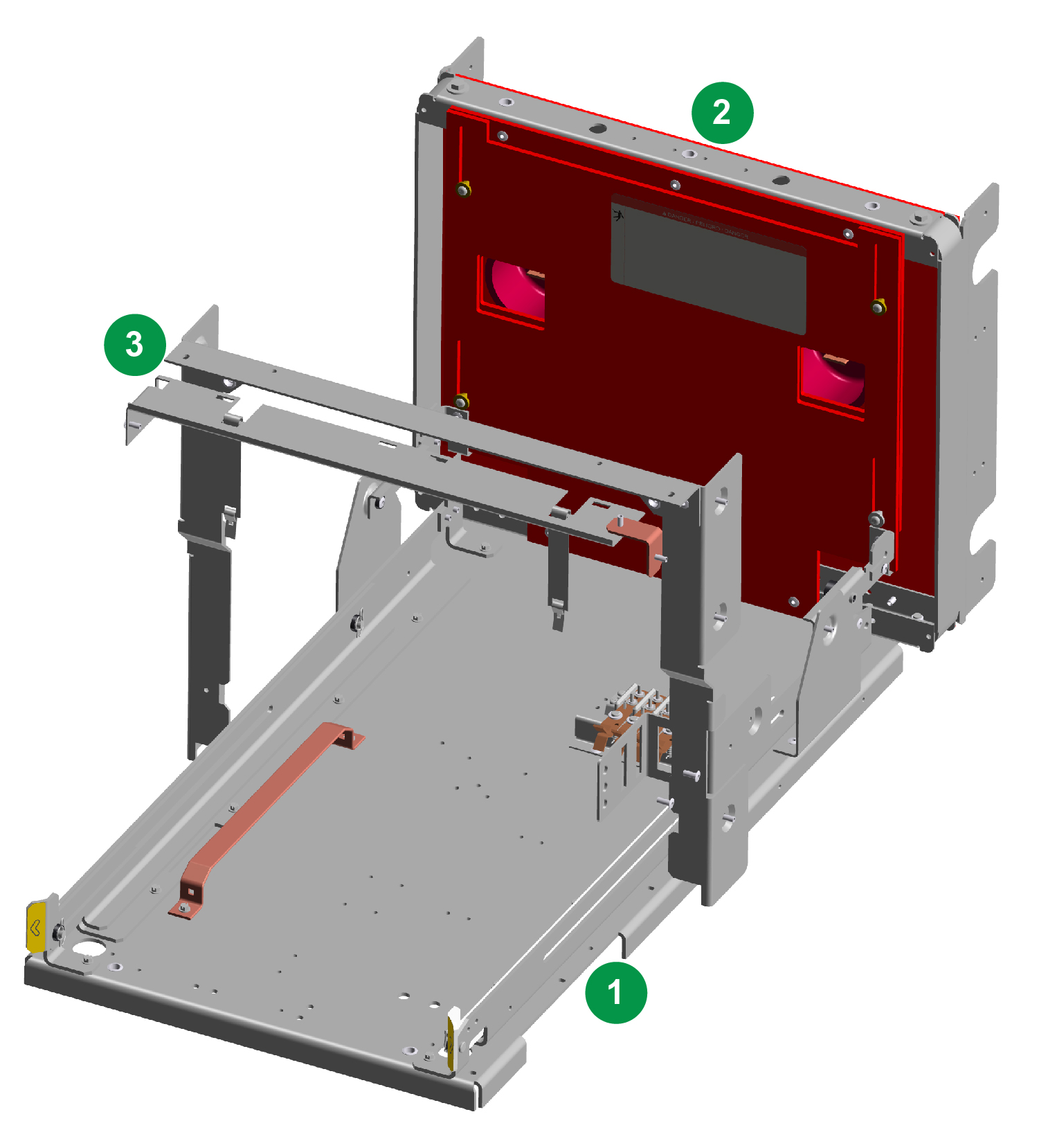
An EvoPacT auxiliary cradle is a separate, rigid, self-contained, bolted structure fabricated of heavy gauge steel which includes the essential items required in a switchgear auxiliary compartment. The cradle mainly consists of three different sub-assemblies, as shown in the figure Typical auxiliary cradle assembly overview. The auxiliary cradle can be configured to house either of the following auxiliary drawers:
-
Control Power Transformers (CPTs)
-
Voltage Transformers (VTs)
The auxiliary cradle sub-assemblies are typically packaged partially assembled with the auxiliary drawer on a dedicated pallet. The auxiliary cradle and drawer components will need to be carefully handled and assembled together from the individual items received. An OEM may incorporate this auxiliary cradle with an auxiliary drawer into the switchgear of their own design and construction. The EvoPacT auxiliary cradle with drawer is a UL Recognized Component. Refer to Schneider Electric document NNZ9886800, SureSeT Medium Voltage, Metal-Clad, Indoor Switchgear User Guide for a detailed description of all auxiliary cradle and drawer features and the operational use.
As a standard, the auxiliary cradle is designed for placement into a minimum of 26 inch (660 mm) wide OEM switchgear or placement into existing field equipment. Consult with a Schneider Electric Services representative for use of the cradle in equipment wider than 26 inches (660 mm).
The standard insulation used in the primary bushing assembly and standoff supports of the auxiliary cradle and drawer is of a Group A material, but the primary bushing assembly and standoff supports may be of the Group B insulation material, if specified (refer to Schneider Electric document NNZ9886800, SureSeT Medium Voltage, Metal-Clad, Indoor Switchgear User Guide for further information on insulation material groups).
 DANGER DANGER |
|---|
|
hazard of electric shock, explosion, or arc flash
Failure to follow these instructions will result in death or serious injury.
|
| DANGER |
|---|
|
hazard of electric shock, explosion, or arc flash
Failure to follow these instructions will result in death or serious injury.
|
Mechanical connection points for auxiliary cradles
The auxiliary cradle must be assembled before being mounted in the OEM switchgear as shown in the figure Connection points of auxiliary cradle sub-assemblies. Use three (3) conical spring washers and three (3) 3/8-16 machine screws SAE Grade 5 (minimum) to connect the auxiliary bushing sub-assembly to the base floor sub-assembly. Refer to the torque values in the Torque Value. Take care to support the auxiliary bushing sub-assembly until the cradle is fully mounted into the OEM switchgear.
 DANGER DANGER |
|---|
|
HAZARD OF ELECTRIC SHOCK, EXPLOSION, OR ARC FLASH
Ensure bolts are torqued per the specifications in section, Standard Fastener Torque Values for the
Switchgear.
Failure to follow these instructions will result in death or serious injury.
|
Connection points of auxiliary cradle sub-assemblies

During the assembly of the equipment into the OEM switchgear, use the provided mounting holes to secure the auxiliary cradle in place. The auxiliary cradle must be secured at both the base floor sub-assembly and the bushing sub-assembly to prevent any movement. Connection points are provided on both left and right sides to be mounted in the OEM switchgear. After the sub-assemblies are assembled together and moved into the OEM switchgear, secure the:
-
Floor sub-assembly at six (6) connection mounting points. Refer to figure Typical auxiliary cradle floor sub-assembly connection mounting points (top view). Use 1/4-20 self-tap screws SAE Grade 5 (minimum), or equivalent strength fasteners. Refer to the torque values in the Torque Value.
-
Bushing sub-assembly at eight (8) connection mounting points. Refer to figure Typical auxiliary cradle bushing sub-assembly connection mounting points (right side view). Use 1/4 inch diameter steel rivets, such as the Avdel® 2761-0821 item, or equivalent strength fasteners.

Typical auxiliary cradle bushing sub-assembly connection mounting points (right side view)
The cross barrier plate of the metal barrier sub-assembly kit may need to be assembled to the two (2) side metal barriers using the two (2) rivets provided in the kit, see the figure Connection points of an auxiliary cradle metal barrier sub-assembly to cubicle frame. The metal barrier sub-assembly kit must be secured in the corresponding OEM switchgear compartment after installing the associated auxiliary cradle base floor sub-assembly and bushing sub-assembly. There are different metal barrier sub-assembly kits supplied depending on the auxiliary cradle specified, such as CPT or VT, selected ratings, etc. So it is critical that the correct metal barrier sub-assembly is used in order to properly ground the fuses and primary side of the CPT or VT as the auxiliary drawer is moved to the disconnected position. Three (3) connection mounting points are provided on both left and right sides to mount the metal barrier sub-assembly in the OEM switchgear compartment, see the figure Connection points of an auxiliary cradle metal barrier sub-assembly to cubicle frame. A CPT auxiliary cradle will also require an additional two (2) mounting connection points for a plate that is used to interlock the secondary molded case circuit breaker located on the CPT drawer and which provides the capability to padlock a CPT application. See the figure Connection points of an auxiliary cradle metal barrier sub-assembly to cubicle frame. Use 1/4 inch diameter steel rivets, such as the Avdel® 2761-0821 item, or equivalent strength fasteners, to secure the barrier sub-assembly in place.
| DANGER |
|---|
|
hazard of electric shock, explosion, or arc flash
Failure to follow these instructions will result in death or serious injury.
|
A static primary discharge ground contact sub-assembly is provided in the corresponding metal barrier sub-assembly for grounding the primary fuses on the auxiliary drawers. A properly sized grounding wire (not provided) will need to be routed from the VT and CPT static ground contact sub-assemblies to the OEM switchgear main ground bus.
On VT auxiliary cradles, the VT static primary discharge ground contact sub-assembly consists of hanging chains and is integrated onto the metal barrier sub-assembly. The OEM switchgear ground wire should be connected to the bottom left metal barrier with a 1/4-20 self-tap screw SAE Grade 5 (minimum), or equivalent strength fastener (not provided). Refer to the figure Front view of auxiliary ground connections for where to connect the VT ground wire.
On CPT auxiliary cradles, the static primary discharge ground contact sub-assembly consists of hanging metal linkages and needs to be mounted a specific distance from the metal barriers. Refer to the figures CPT left side view and CPT right side view for details on where to mount the CPT static ground contact sub-assembly. The OEM switchgear ground wire should be connected to the front, upper left, side rivet prior to installation. Refer to the figure Connection points of an auxiliary cradle metal barrier sub-assembly to cubicle frame and the area circled in green in the figure CPT right side view for where to connect the CPT ground wire.
Connection points of an auxiliary cradle metal barrier sub-assembly to cubicle frame
| A | Metal barrier sub-assembly mounting locations (6 points) (both CPT and VT) |
| B | Cross barrier plate and assembly location (2 points) (both CPT and VT) |
| C | Plate for secondary molded case circuit breaker interlock mounting locations (2 points) (CPT only) |
| D | Static primary discharge ground contact sub-assembly mounting locations (3 points) (CPT only) |
| E | OEM switchgear ground wire connection location (1 point) (CPT only) |
| F | OEM switchgear ground wire connection location (1 point) (VT only) |
CPT left side view
CPT right side view
Front view of auxiliary ground connections
Electrical connection points for auxiliary cradles
The auxiliary cradle provides connections points to connect to the OEM switchgear ground bus. The auxiliary drawer is continuously grounded through a ground bus mounted on the base floor sub-assembly of the auxiliary cradle. An OEM switchgear ground wire can be connected (hardware not provided) to this ground bus and routed to the OEM switchgear main ground bus, see the figure Front view of auxiliary ground connections. Refer to the previous section, Mechanical connection points for auxiliary cradles, on where to connect an OEM switchgear ground wire to the auxiliary cradle metal barrier sub-assembly.
The auxiliary cradle contains provisions to connect to the OEM switchgear primary bus with either an entry point located on the top of each of the auxiliary bushings or with an entry point located on the bottom of the auxiliary bushings, see the figure Connection points on auxiliary compartment. The auxiliary cradle bushing sub-assembly has a copper bus bar primary contact (1.125 in. x .125 in.) in each phase with a 1/4-20 machine thread stud and nut to connect to the OEM switchgear primary bus, see the figure Connection points on auxiliary primary contact. The primary contact bus, in each of the auxiliary bushings, has a 1/4-20 threaded nut allowing for horizontal connections with the OEM switchgear connection using a bolt (not provided). The bus also has a 1/4-20 threaded stud allowing for a vertical connections with the OEM switchgear connection using a nut (not provided). For mounting an electrical connection, refer to the torque values in Torque Value.
| DANGER |
|---|
|
HAZARD OF ELECTRIC SHOCK, EXPLOSION, OR ARC FLASH
Failure to follow these instructions will result in death or serious injury.
|
Typical polyvinyl chloride boots are supplied with the auxiliary cradle to insulate the primary bus connection. Install the supplied boots over the auxiliary cradle primary contacts in the auxiliary bushing sub-assembly and OEM switchgear primary bus connections. Close each boot with tie wraps. It is recommended that the OEM switchgear primary bus connections be designed to have these boots overlap with insulation on the OEM switchgear connections. The switchgear primary connection insulation and boots form an integral insulating system for the equipment to meet the dielectric ratings of the equipment. The insulating boots must be in place and properly closed before energizing the equipment.
Connection points on auxiliary compartment

| A | Bushing sub-assembly orientated with bottom opening |
| B | Bushing sub-assembly orientated with top opening |
Connection points on auxiliary primary contact

| A | 1/4-20 threaded nut for horizontal connection with OEM switchgear bolt |
| B | 1/4-20 threaded stud for vertical connection with OEM switchgear nut |