
Splice Points
When you locate a splice, Wavepoint provides three tabs: Details, Circuits, and Assets.
-
Do you not see the Details and Assets tabs?
-
Most likely, you have selected the splice on the map, but have not yet clicked the name to further open it and see its internal information.
-
Click the name once, and the application displays the Details and Assets tabs.

-
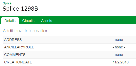
Details
This tab displays the splice's high-level, GIS attributes.
Circuits
This tab provides information regarding circuits that pass through the splice.
Use the Filter field to refine the list.

Click the circuit name to open its information page.
Click the View button to see the fiber connections that compose that circuit at the splice.
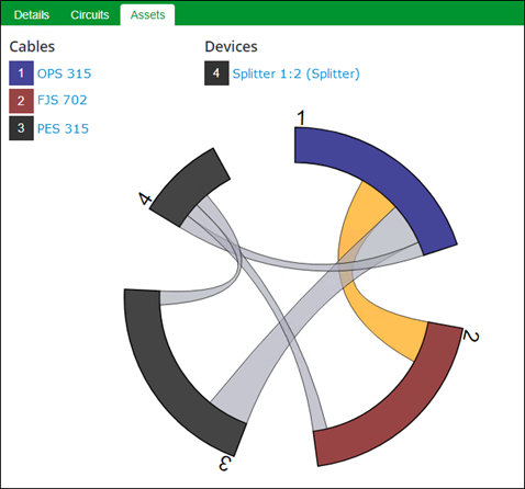
Assets
This tab helps you visualize the cables, strands, and devices present at the splice. Use the Assets tab (left pane) in conjunction with the Connections tab (right pane) to view splice and device connectivity.
-
Semi-circular components composing the edge of the ring represent cables and devices participating in this splice location.
-
Click the connections among the cables and devices in the ring to display strand connectivity in the Connections tab on the right pane.
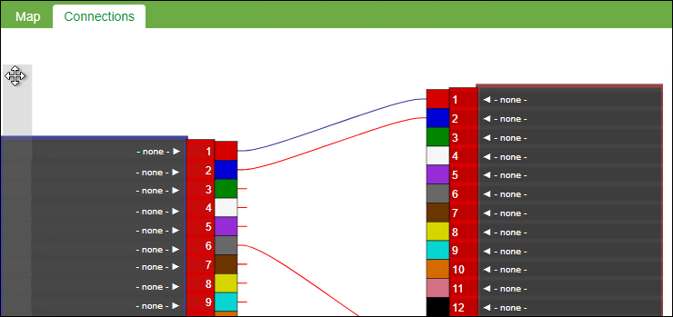
Connections Tab Display Options
In the Connections tab, you can manipulate the view in variety of ways:
-
On the outer edge of either cable, click and hold to re-position the cable.
For example, in the following image, the cable on the left is too low to see the connections:
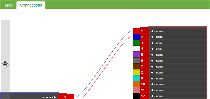
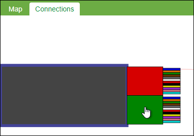
To correct this, click and hold the outer edge, then drag up to move the cable into a more convenient position:
-
Click on the buffer tube colors to expand them.
-
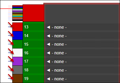
If a strand has a stub, it means that strand is connected to another, but not in the currently visible cable on the opposite side. Click a strand's color to switch the view to display the other side of its connection.
 IMPORTANT: Are you not seeing connections that you know exist in Fiber Manager? It could be because the map service was published with an allowable records maximum set too low. This is particularly true with high-count cables. See the Configuration topic Publish the Map Service for more information.IMPORTANT: Are you not seeing connections that you know exist in Fiber Manager? It could be because the map service was published with an allowable records maximum set too low. This is particularly true with high-count cables. See the Configuration topic Publish the Map Service for more information.
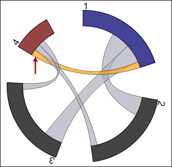
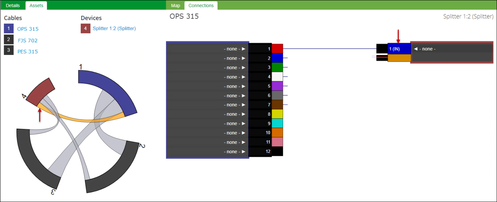
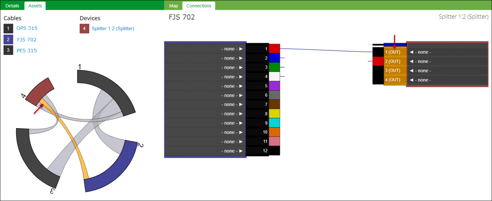
Viewing Splitters and Passive Devices
The same display options discussed above are available for splitters and passive devices. The primary difference is the device displays whether it is an “in” port or an “out” port.
-
For example, in the following image you can see the red fiber from the OPS 315 cable is connected to the in port.
-
Using the same example, below you can see out port 1 is connected to the red fiber in the FJS 702 cable.
-
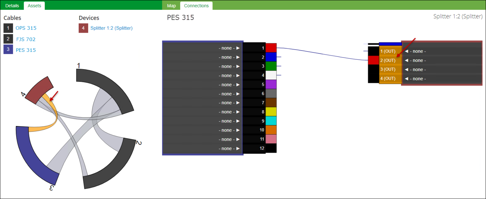
Finally, you can see out port 2 is connected to the red fiber in the PES 315 cable.
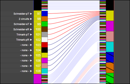
Viewing Circuits
Circuit names are found near the strand numbers.
When viewing circuits, keep the following in mind:
-
If no circuit is present, the name “none” is visible near the strand number.
-
Strands belonging to a circuit appear in red.
-
For any strand on the Connections tab, click the circuit's name (or the name “none” if no circuit is present) to populate the left pane with trace options and strand information. Then, you can run a Full Path trace for that circuit or fiber.