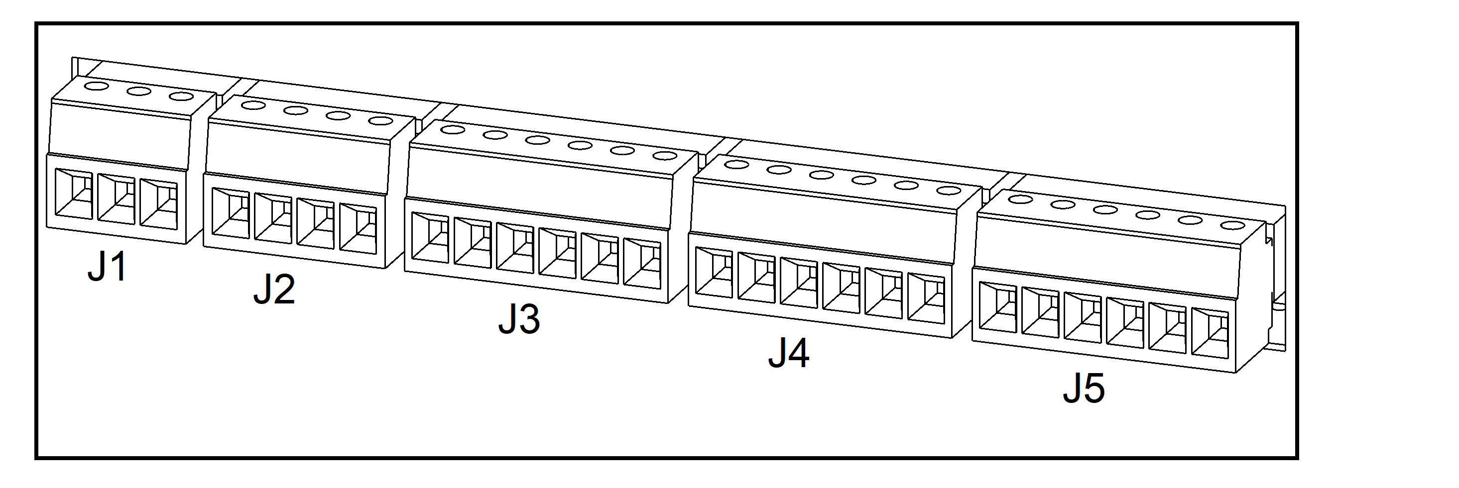
Connect the Signal Cables to the Input Contacts and Output Relays
- Connect the Class 2/SELV signal cables from the building EPO to terminal J2-3 and J2-4 in the UPS. The EPO circuit is considered Class 2/SELV. Class 2/SELV circuits must be isolated from the primary circuitry. Do not connect any circuit to the EPO terminal block unless it can be confirmed that the circuit is Class 2/SELV.
- Connect the Class 2/SELV signal cables to the input contacts and output relays in the UPS. Do not connect any circuit to the input contacts unless it can be confirmed that the circuit is Class 2/SELV.
- Connect the signal cables from the auxiliary products to the UPS. Follow the instructions in the auxiliary product manuals.
| Terminal | Function | Diagram | |
|---|---|---|---|
| J1-1 | Configurable output (30 VDC / 3 A) |
NC |  |
| J1-2 | NO | ||
| J1-3 | COM | ||
| J2-1 | Configurable input (24 VDC / 1 mA) |
Input_3 |  |
| J2-2 | GND | ||
| J2-3 | EPO normally closed (24 VDC / 1 mA) |
EPO NC | |
| J2-4 | +24 V | ||
| J3-1 | Configurable output (24 VDC / 400 mA) |
+24_DRY |  |
| J3-2 | GND | ||
| J3-3 | Configurable input (24 VDC / 1 mA) |
Input_2 | |
| J3-4 | GND | ||
| J3-5 | Ambient temperature signal | Temp 2 | |
| J3-6 | Temp_COM | ||
| J4-1 | External battery temperature signal | Temp 1 |  |
| J4-2 | Temp_COM | ||
| J4-3 | Configurable
input* / (24 VDC / 1 mA) |
Input_1 | |
| J4-4 | — (24 VDC / 400 mA) | +24 V | |
| J4-5 | — (24 VDC / 400 mA) | +24 V | |
| J4-6 | — | GND | |
| J5-1 | Configurable output (30 VDC / 3 A) |
NC |  |
| J5-2 | NO | ||
| J5-3 | COM | ||
| J5-4 | Bypass backfeed trip (30 VDC / 3 A) |
NC | |
| J5-5 | NO | ||
| J5-6 | COM | ||

