
Specifications
Input Specifications
| Commercial reference | PMM400-ALAX PMM400-ALA PMM400-CUB |
PMM500-ALAX PMM500-ALA PMM500-CUB |
|---|---|---|
| kVA | 400 | 500 |
| Connections | 3-wire (3P + PE) | |
| Input voltage (V) | 480 | |
| Input current (A) | 493 | 617 |
| Frequency (Hz) | 60 | |
| Maximum short circuit rating | 65 kA RMS symmetrical at 480 V | |
Output Specifications
| Commercial reference | PMM400-ALAX PMM400-ALA |
PMM400-CUB | PMM500-ALAX PMM500-ALA |
PMM500-CUB |
|---|---|---|---|---|
| kVA | 400 | 500 | ||
| Connections | 4-wire (3P + N + PE) | |||
| Output voltage (V) | 400 or 208 | 208 | 400
or 208 415 or 216 |
415 or 208 |
| Output current (A) | 1110
at 208 V 577 at 400 V |
1110 at 208 V | 1388
at 208 V 1336 at 216 V 722 at 400 V 696 at 415 V |
1388 at 208 V 696 at 415 V |
| Frequency (Hz) | 60 | |||
| Output current protection (A) | 250-600 | |||
| Branch output (A) | 250, 400, 600 | |||
Required Upstream Protection for PDU Systems with a Main Input Switch MIS
 DANGER DANGER |
|---|
|
Hazard of electric shock, explosion, or arc flash
For PDU systems with a main input switch MIS, it is mandatory
to install an upstream OCPD. Refer to the following table for the
recommended upstream OCPD model or use an upstream OCPD that is rated
to comply with the maximum current setting specified.
Failure to follow these instructions will result in death or serious injury.
|
| Commercial reference | PMM400-ALAX | PMM400-ALA | PMM400-CUB | PMM500-ALAX | PMM500-ALA | PMM500-CUB |
|---|---|---|---|---|---|---|
| kVA | 400 | 500 | ||||
| Upstream OCPD | PJX36080UXXX (Ir=504A max) | PJX36080UXXX (Ir=640A max) | ||||
Recommended Cables Sizes
| DANGER |
|---|
|
hazard of electric shock, explosion, or arc flash
All wiring must comply with all applicable national and/or
electrical codes.
Failure to follow these instructions will result in death or serious injury.
|
Input and Output
| Device | Main input device MID | Main output device MOD | |||
|---|---|---|---|---|---|
| Type | 3-pole, switch (MIS) for 400/500 kVA | 3-pole, circuit breaker (MIB) for 400/500 kVA | 3-pole, circuit breaker (MOB) for 400 kVA | 3-pole, circuit breaker (MOB) for 500 kVA | |
| Rating | 800 A, 600 V | 800 A, 600 V at 80% | 1200 A, 600 V at 100% | 1600 A, 600 V at 100% | |
| Brand | Square D by Schneider Electric | ||||
| Model | PJF36000S80 | PJF36080U33A | RJF36120CU33A | RJF36160CU33A | |
| (Standard) Mechanical terminal wire range (aluminum/copper) | 3 x 3/0 AWG to 500 kcmil | NA | NA | ||
| Mechanical wire bending space | 363.22 mm (14.3 in) | NA | NA | ||
| (Option) Compression terminal wire range (aluminum/copper) | 2
x 250 kcmil, NEMA 2 hole (1/2 inch bolt) - wire bending space: 279.4 mm (11 in) 2 x 350 kcmil NEMA 2 hole (1/2 inch bolt) - wire bending space: 269.24 mm (10.6 in) 2 x 500 kcmil NEMA 2 hole (3/8 inch bolt) - wire bending space: 279.4 mm (11 in) |
NA | NA | ||
Branch Circuit Breaker
| Rating | Branch circuit breaker | Breaking capacity | Terminal wire range (aluminum/copper) | Wire bending space | |
|---|---|---|---|---|---|
| 240 V | 480 V | ||||
| 250 A at 80% | JDA36250U33X | 25 kA | 18 kA | 3/0 AWG to 350 kcmil | 487.68 mm (19.2 in) |
| 250 A at 100%* | JDA36250CU33X | ||||
| 250 A at 80% | JGA36250U33X | 65 kA | 35 kA | ||
| 250 A at 100%* | JGA36250CU33X | ||||
| 400 A at 100% | LGA36400CU33X | 2 x 3/0 AWG to 500 kcmil | 386.08 mm (15.2 in) | ||
| 400 A at 80% | LDA36400U33X | ||||
| 400 A at 80% | LDA36400U33X | 25 kA | 18 kA | ||
| 400 A at 100% | LDA36400CU33X | ||||
| 600 A at 80% | LGA36600U33X | 65 kA | 35 kA | ||
| 600 A at 80% | LDA36600U33X | 25 kA | 18 kA | ||
Conduit Area
| Cable entry system | Conduit area mm (in) |
|---|---|
| Top cable entry incoming cables | 321 x 212 (12.64 x 8.34) |
| Top cable entry outgoing cables (distribution) | 200 x 957 (7.8 x 37.6) |
| Bottom cable entry incoming cables | 127 x 280 (11 x 5) |
| Bottom cable entry outgoing cables (distribution) | 181 x 934 (7.1 x 36.78) |
Bottom Cable Entry System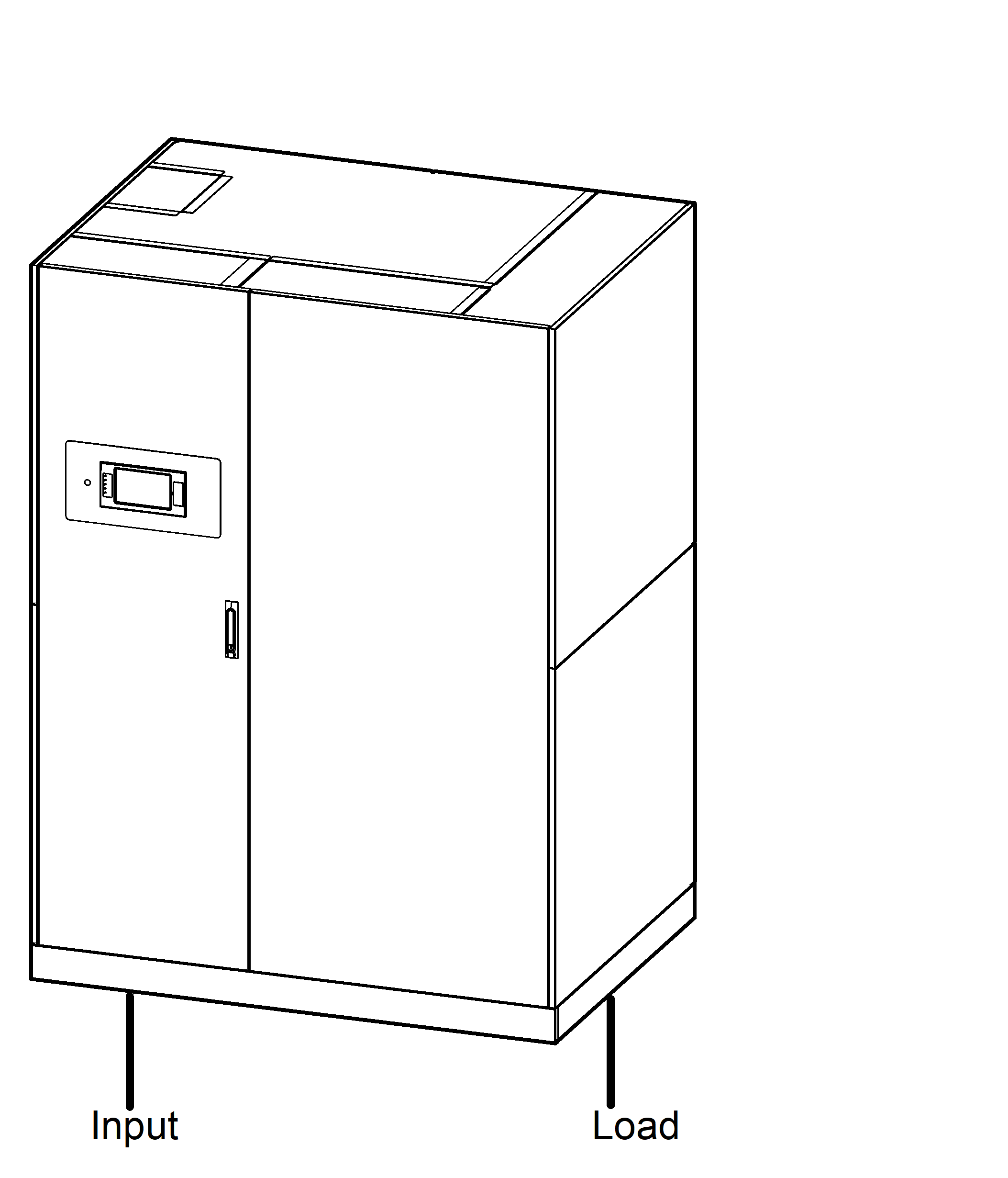 |
Top Cable Entry System |