
Configuration Settings for Viewer Templates
Viewer Configuration
-
Once the VertiGIS Studio Web Designer web page has been opened, you can configure your viewer by selecting a template. Click on the template you wish to work with, and the Web Designer opens with the template you selected. An important difference between ArcFM Web 4.x and 5.x is that the notion of adding Properties, such as ArcFMTracingCapabilities, no longer exists. This functionality is automatically added with workflows, which are installed on tools on the Toolbar.
-
For help with the configuration process, click the Help button on the left side to access VertiGIS Studio Web resources.
-
The layout of a template consists of rows and columns configured to give the appearance you desire. Rows and columns can be layered on top of each other to further customize the look of your map. In addition, components can be added to customize the functionality and behavior of your map.
-
If you aren’t certain where a component resides in the Components tree, click on the Enable Selection of Components button and click on the highlighted area of the map. The Components tab changes to display the area of the map you selected. This makes it easier to drill down to the area you’re interested in working with.
-
At any time, you can click on the pop out Preview Window button so you can see the Viewer as users see it. Once the map has popped out, you cannot perform any configuration. You must close the popped-out window to resume configuration.
General Configuration Steps
This section provides the general steps involved in configuring a viewer. To see more detailed steps, refer to the Specific Configuration Example section below.
There are six templates provided by Schneider Electric, three for geometric networks and three for the Utility Networks. They are:
-
Geometric Network Templates:
-
Electric.Trace.Web
-
Gas.Trace.Web
-
Water.Trace.Web
-
-
Utility Network Templates:
-
Electric.Trace.UN.Web
-
Gas.Trace.UN.Web
-
Water.Trace.UN.Web
-
To install a template, perform the following steps:
-
Open the VertiGIS Studio Web Designer.
-
Select a new blank template.
-
Click File > Save As.
-
Type a Title and click Save.
-
Click File > Upload App.
-
In the resulting dialog box, click Select File.
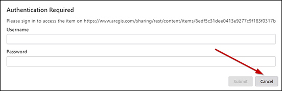
Note: When saving, a dialog might display requesting to provide login credentials to an ArcGIS URL. Click Cancel on this dialog, and the Save process will continue. This URL is not valid and is a placeholder within the configuration file.
_DD00870989.jpg)
-
Navigate to the location of the zip file and select it.
-
Click Open.
-
Click Submit.
-
Add a map to your viewer by clicking Map under the Components list.
-
Under the Map Settings section, click on the Select button.
-
Search for the desired map and select it.
-
Click Select.
Note: Installing a new Template does not override any customizations on the Viewer.
To install a new workflow, perform the following steps:
-
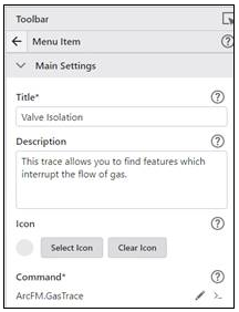
Open the appropriate Menu Item. For example, to access the workflow for a gas valve isolation trace, open Toolbar > Main Setting > Menu Items > Gas Traces > Valve Isolation. Sample arguments can be found in the Trace_Workflow_Arguments folder contained within the GeometricNetworkFiles or UtilityNetworkFiles directories, whichever is appropriate for your business.
-
Under the Command heading, click the pencil button to edit that value.
-
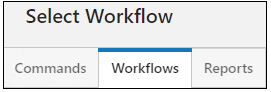
Click the Workflows tab.
-
Select the desired workflow and click Select. Workflows for electric, gas, and water utilities are provided by Schneider Electric, along with a workflow to clear the trace.
-
Edit the Input Arguments box by copying and pasting the appropriate sample argument. Be sure to perform either of the following edits to the arguments according to the type of network you are using. If using a Geometric Network, perform the following edits to the arguments:
-
For electric, edit the ServiceUrl, traceType, protectiveDeviceLayerIDs, and mapServiceId.
-
For gas, edit the serviceUrl, traceType, mapServiceId, valveLayerID, and distributionMainId.
-
For water, edit the serviceUrl, traceType, mapServiceId, valveLayerID, and distributionMainLayerId.
If using a Utility Network, perform the following edits to the arguments:
-
For electric, gas, or water, edit the addGraphicsWorkflowUrl.
Note: Performing traces on the UN through ArcFM Web requires referencing named trace configurations that are included with each release as workflow arguments. Users may create their own custom named trace configurations in ArcGIS Pro that can then be exported for use in ArcFM Web XI. See Esri’s Named Trace Configurations documentation for details around how to create Named Trace Configurations.
-
-
Be sure to save your changes from the File menu on the left-hand side of the Designer.
Specific Configuration Example
VertiGIS Studio Web provides a variety of base templates to get you started with viewer configuration. The following steps will walk you through this process, using the “Web GIS – Default” template for an electric geometric utility as an example.
Select a Viewer Template
-
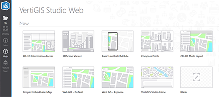
Open VertiGIS Studio Web either via their apps page or from your installation. In either case, you will be prompted to log in to ArcGIS Online or Portal. After logging in, the initial screen looks like this:
_DD00870986.jpg)
-
Click Web GIS – Default to open the template.
-
Click File > Save As, type a title for your Viewer in the Title field, then click Save.
Load a Viewer Template
-
From the left-hand toolbar, click File > Upload App. The Upload backup dialog box appears.
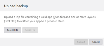_DD00870985.jpg)
-
Click Select File and navigate to the location of the Viewer Templates directory. Select ElectricTemplate_GN.zip and click Open.
-
The Upload backup dialog displays your selected template. Click Submit. This installs several components in the viewer, any of which can be further customized if desired.
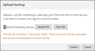_DD00871004.jpg)
Notes Regarding Configuration in Studio Web
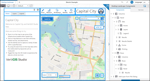
Before proceeding with the actual configuration of your viewer, let’s go over a few things regarding the layout and functionality of the VertiGIS Web Studio window.
-
Viewers are laid out in a series of rows and columns. This allows for a wide variety of customizations. In our example, we aren’t going to change the layout, merely the elements defined within it.
-
There are three main parts to the Web Studio window. On the far left is the Web Studio toolbar. It contains icons for actions related to the Viewer and application as a whole.

-
In the middle of the window is the Viewer preview. This is where changes to the viewer display as you make the changes to help ensure your viewer is configured as desired. When a change is made, a circle symbol appears at the end of your viewer’s Title (as illustrated in the screenshot below), indicating there are unsaved changes. To save your changes, click File > Save and the circle symbol will then be removed.
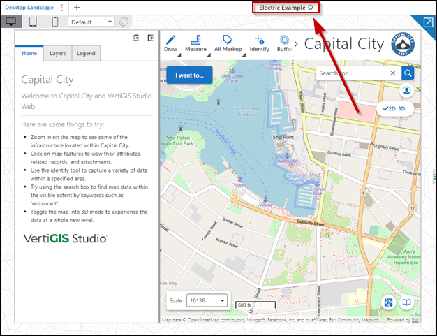_DD00871002.jpg)
-
On the far right of the screen is the Desktop Landscape Components area where all the actual configuration takes place. The Components tab is laid out in a hierarchical arrangement for your viewer. Sideways-facing arrows can be tipped to display the hierarchy under them.
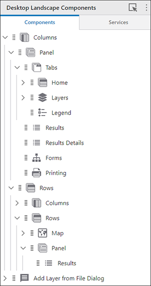_DD00871001.jpg)
-
To edit a configuration item, click on the item in the Components tab. Alternately, you can click on the helper icon on the right side of Desktop Landscape Components. The viewer area changes to show an assortment of outlined boxes (outlined in blue in the image below). Click on the desired area to open the associated component.
_DD00871000.jpg)
Select a Map Service
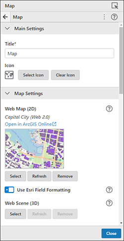
To complete the viewer configuration, you'll need to specify the map service for your viewer.
-
On the Components tab, scroll down and click on Map component to display the Map tab.
_DD00870999.jpg)
-
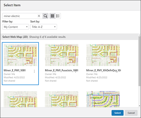
Click the Select button. The Select Item dialog box displays where you can search for and select your desired map service. Once you locate your map service, select the map service and click the Select button. If you previously applied Tags to your services, you can also use those Tags in the Search field (as illustrated in the screenshot below) to refine the list of available map services.
_DD00870998.jpg)
-
Your map service is now visible in the main map area. There is nothing further to do with the Map tab. Additional customizations can be made if you'd like. Scroll through this tab to see what customizations are available.
-
Click Close on the Map tab once you are done configuring your map. The main Components tab displays again.