
Setting up the ArcFM Web Configuration
Configure the Home Tab
The Home tab is located on the left side of your viewer window and it can also be customized. You can edit both the image and the text on this screen via the Home item on the Components tab. The following instructions add a logo image.
-
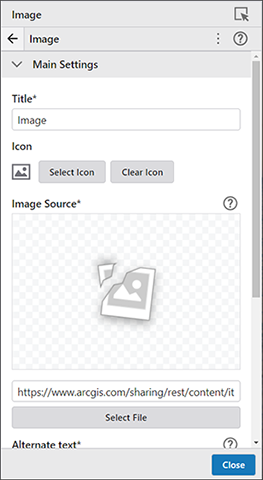
From the Components tab, click on Image. The Image tab displays.
_DD00870982.jpg)
-
Click the Select File button.
-
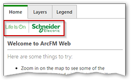
Navigate to the location of the image file, select it and click Open. The image is applied to the Home tab.
_DD00870981.jpg)
-
Click Close to return to the main Components tab.
-
If you want to change the text that appears on the Home tab, click Home (Text) on the Components tab, make the desired edits and click Close.
Configure Tracing Workflow
The final piece of configuring the viewer is to set up the workflows for tracing. The basic structure is included in the template that was initially uploaded, but there are a few specifics that need to be configured. The following steps need to be completed to finish the configuration.
-
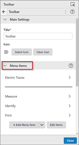
Click on Toolbar from the Components tab. Then click on Electric Traces under Menu Items.
_DD00870980.jpg)
-
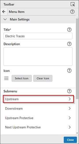
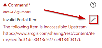
Click Upstream under the Submenu section.
NOTE : You might see Invalid Arguments warnings. They indicate the Item they are pointing to does not exist. These are replaced with valid URLs in the next step.
_DD00870979.jpg)
-
Click on the pencil to open the Select Command dialog.
_DD00870978.jpg)
-
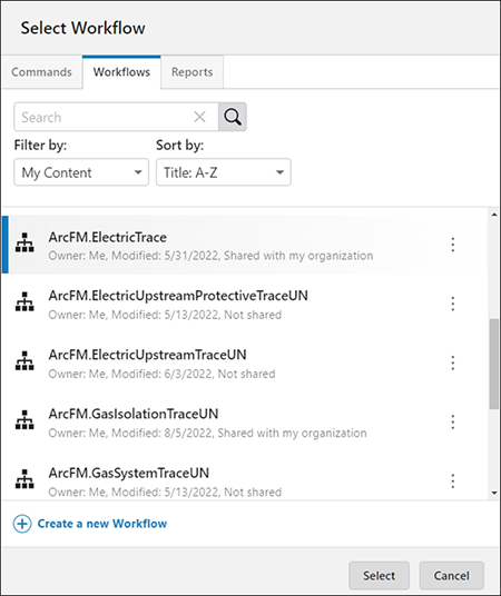
Click on the Workflows tab, then click on the ArcFM.ElectricTrace workflow and click Select.
_DD00870977.jpg)
-
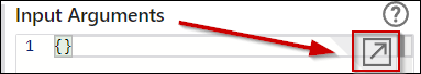
The workflow is added to the viewer, but the arguments to the workflow need to be specified. To do this, click the arrow to the right of Input Arguments. This opens an Input Arguments text box for you to copy and paste the necessary arguments into.
_DD00870976.jpg)
-
In File Explorer, navigate to the location of the Trace_Workflow_Arguments directory. This is located in the Supplemental Files folder > GeometricNetworkFiles or UtilityNetworkFiles > Trace_Workflow_Arguments.
- If using a geometric network, open the ElectricTraceOptions_GN
file with a file editor such as Notepad++ and follow the steps below:
-
Edit the serviceUrl element to point to the desired map server.
-
Edit the traceType element to be Upstream. This value needs to be changed for each different trace type that is configured.
-
Edit the traceTitle element to match the traceType value. This value is displayed at the top of the Trace tab when a trace runs so users can easily tell which type of trace is running.
-
Edit the protectiveDeviceLayerIDs element to contain the layer IDs for protective devices in this map service.
-
Edit the mapServiceId element to contain the name of the map service.
-
-
If using a utility network, open the ElectricUpstreamProtectiveTraceOptions_UN file with a file editor and follow the steps below:
-
addGraphicsWorkflowUrl — the URL path to the AddTraceGraphics item in your Portal
-
namedConfiguration — the named configuration, created in ArcGIS Pro, for the specific trace type being configured
-
geometryServiceURL — the URL path to the geometry service
-
Replace the current 'traceConfiguration' section of the example argument file with the equivalent configuration section from your named trace configuration. Be sure to include all content between the curly braces. See how to export a named trace configuration from ArcGIS Pro.
-
-
Once these edits are completed, copy the entire contents of the file and paste into the Input Arguments window that is open in Studio Web.
-
Click the Close button.
-
Save your viewer.
The above steps need to be repeated for each trace type. Click Pop out preview window at any time during this process to see the viewer as users will see it. This provides the opportunity to ensure the viewer looks and behaves as expected. When the viewer is popped out, you cannot perform any configuration. You must close the popped-out window to resume configuration.
Additional Configuration
To add an item to the toolbar or I Want to… menu, perform the following steps:
-
Open the Toolbar or I Want to Menu pane.
-
Under the Menu Items section, click Add Menu Item.
-
Select the appropriate tab (Commands, Workflows, or Reports), based on what you want to add.
-
Select the desired item and click Select.
-
To further customize the menu item, click the right arrow (>) to open a new pane.
-
Make any desired changes and save your edits from the File menu on the left-hand side of the Designer. Click the Close button when you’re finished.
NOTE: If you include the Buffer Identity tool, be aware you also need the Clear Drawings tool to remove the buffer graphic from the map.
To reorder the toolbar or I Want to… items, perform the following steps:
-
Open the Toolbar or I Want to Menu pane.
-
Under the Menu Items section, without selecting any entries, click Edit Items. The view changes, offering options to move or delete items.
_DD00870975.jpg)
-
Perform the desired actions. To reorder the toolbar items, click and drag each item to the desired location.
-
When finished, click Done. Save your edits from the File menu on the left-hand side of the Designer.
To change the map, perform the following steps:
-
Open the Map pane.
-
Under the Map Settings section, click on the Select button.
-
Search for the desired map and select it.
-
Click Select.
NOTE: Only one map service can be used in 2D view. However, that map service can contain multiple other services. To add a component to the map, perform the following steps.
To add a component to the map, perform the following steps.
-
Click Add Component.
-
Select the desired tab based on what you want to add.
-
Locate the item you want to add.
-
Click and drag it over to the Components tab, under the desired area.
-
Click on the new item to customize it. For example, you can select where the item is to be located on the map.
Deploy Application
Once you are satisfied with the configuration of a viewer and you are ready to give it to your users, complete the following steps:
-
Make sure the Viewer has been saved.
-
Click Deploy, followed by the three vertical ellipses above the Deploy to Production button.
-
Click Sharing Permissions.
-
Make sure all elements are at the desired sharing level. To change permissions, click on the item, it then opens in ArcGIS Online or Portal for ArcGIS and you can set the Sharing Level.
Click the circular arrows button in the top right corner to refresh your list of elements.
-
Click Close when all elements are set to the desired permissions.
-
Click the Deploy to Production button.
-
Click the Deploy button. Once this process is complete, the elements exist in ArcGIS Online or Portal for ArcGIS with (prod) at the end of the name.
NOTE: After the viewer has been deployed, it is necessary to set sharing permissions on all deployed items as those permissions are not automatically inherited. For each item that has (prod) appended to the name in ArcGIS Online or Portal for ArcGIS, click the Sharing button, select the desired sharing level and click Save.