
Installation
Correct installation of FlexSeT switchboards is essential for proper operation of all switchboard components. Study the associated instruction books and all drawings carefully. In most cases, all drawings are sent to the purchaser before a switchboard is shipped to enable adequate planning.
Location
Find the designated area on the building floor plan where the switchboard will be installed. The location chosen for installation should provide working clearances complying with Section 110-26 of the National Electrical Code® (NEC®).
- Front-accessible switchboards require field connections, including mains, branches, ground bus, and neutral bus, to be accessible and maintainable from the front.
- For switchboards having rear ventilation, allow a minimum 1/2 in. (13 mm) clearance between the rear of the switchboard and the wall for proper ventilation. Equipment drawings identify switchboards requiring rear or side access.
- Switchboards that require rear access for installation, field connections, or maintenance (such as filter replacement), require 30 in. (762 mm) of working space per NEC 110-26.
- If the switchboard is in a wet location or outside of the building,
enclose it in an outdoor enclosure or equipment to help prevent moisture
or water from entering and accumulating within the enclosure.
Install portable electric heaters of approximately 250 W per vertical section in both indoor-type and rainproof-type switchboard enclosures for adequate protection during storage.
- Outdoor-rated switchboards drain to the rear, so there must be at least a 1/2 in. (13 mm) clearance between the rear of the switchboard and a wall or other obstruction for proper drainage.
Foundation Preparation
The floor or foundation must be strong enough to support the weight of the switchboard without sagging. The surrounding floor area must gently slope toward a drain.
FlexSeT switchboards are assembled on true and level floors at the assembly plant. For correct bus bar alignment, the mounting pad or final installation site must be smooth and level. If parallel steel floor channels are imbedded for mounting the switchboard, take extra care to make sure the floor channels are level over their entire length to avoid distortion of the switchboard structure. Each channel must be level with the finished floor.
When pouring the foundation, make provisions for conduits entering the switchboard from below and carrying the incoming and/or outgoing cables, control wiring, and ground cable. The bottom view in the equipment drawing shows the available conduit area for correct layout.
Conduits should project above the finished floor by about 2 in. (51 mm). However, to simplify moving the shipping sections into place, install the conduits flush with the concrete and, after the sections are in their final position, add the appropriate extension sleeves. Otherwise, raising the shipping section on timbers or lifting it by a crane to clear the conduit hubs will be necessary. Before pouring the foundation, consider installing additional conduits for future circuits.
Switchboard Preparation
Remove dirt and debris from the foundation and surrounding area before moving the switchboard into final position.
Remove all packing materials. If the switchboard is equipped with a bottom closure plate in each vertical section, remove and retain the plates for reuse. When bottom closure plates are furnished, the customer must make any holes necessary for conduit entering the bottom of the switchboard. After making the holes, reinstall the closure plate.
General Installation
| NOTICE |
|---|
|
HAZARD OF IMPROPER STRESS ON BUS
Level and align adjacent shipping sections with one another.
Check for proper alignment of the through bus bridge.
Failure to follow these instructions can result in equipment
damage.
|
Install the switchboard into its final position by leveling progressively each section and bolting the frames together, if separated. Position shipping sections as follows:
- Maneuver each shipping section into the desired position using the procedures under “Handling”.
- Carefully lower the section over the conduit stubs to comply with the “available conduit area” as shown in the bottom view of the equipment drawings. Otherwise, there might not be sufficient cable bending space.
Joining Shipping Sections–Outdoor Switchboards
-
Position each adjacent section, carefully leveling and aligning it with the previous section.
-
Remove the front panels and rear access panels, providing access to bolt adjacent sections together (see ).
Joining Shipping Sections–Outdoor Switchboards
-
Remove five 0.5 in. (13 mm) diameter knockouts from the front vertical corner channel (only on bolt head side) and five from the rear vertical corner channel (a total of ten per frame side), as indicated by the arrows in .
-
Position each adjacent section, carefully leveling it and aligning it with the previous section. The only gasket required between sections is provided across the height of the rear corner channel.
-
Place the ten bolts (3/8-16 x 1 in.) provided in the FLEXBRIDGE2000 kit through the holes created in step 3 to join adjacent sections.
-
Remove four 0.31 in (8 mm) diameter knockouts from each front extension (a total of eight).
-
Place hardware provided in the FLEXEN3ACAP kit on the front extensions as in , Detail C.
-
Make the bridge connection to the preceding section.
-
Install the center top cap provided in the FLEXEN3ACAP kit (see , Detail A).
-
Replace and secure the front and rear panels removed in step 2.
Verify Sealing Hardware
Doorstop Instructions–Outdoor Switchboards
 WARNING WARNING |
|---|
|
Hazard of Blunt Force or pinch injury
Failure to follow these instructions can result in death, serious injury, or equipment
damage.
|
-
Locate and lift the far-right side of the doorstop out of the base channel.
-
Rotate the doorstop towards open such that the far-right side aligns with the open hole at the bottom of the door (see Doorstop Insertion).
-
Insert the doorstop in the open hole at the bottom of the door.
Doorstop Insertion
Gasket Inspection–Outdoor Switchboards and NEMA 2 Point of Utility Connection Public Utilities Commission (Canada) (PUC) Main Switchboards
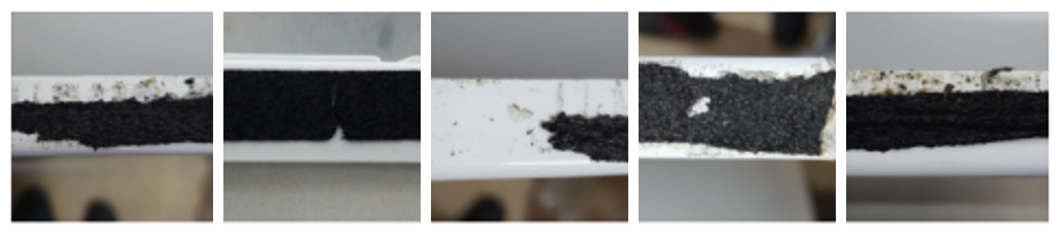
When parts are removed for installation or maintenance purposes (see Side Panels Removed), make sure the gasket is not damaged as shown in Example of Damaged Gaskets.
Side Panels Removed
Parts with Gaskets in NEMA 2, PUC Main
 DANGER DANGER |
|---|
|
HAZARD OF ELECTRIC SHOCK, explosion, OR ARC FLASH
Replace the damaged gasket.
Failure to follow these instructions will result in death or serious injury.
|
Example of Damaged Gaskets
Joining Shipping Sections–Indoor Switchboards
- Position each adjacent section, carefully leveling and
aligning it with the previous section. If lifting straps are provided,
completely remove them from the sides being bolted together so the
sections can be joined flush.
Leave the other lifting straps on the switchboard if their removal is not required to join adjacent sections flush.
- Remove the front panels and rear access panels, providing
access to bolt adjacent sections together (see Joining Indoor Switchboard Sections).NOTE: On NEMA 2 enclosures, inspect the gasket installed on the side flange of the driphoods and make sure that the gasket is not damaged, examples of damaged gasket is shown in Example of Damaged Gaskets.
- Ten bolts (3/8-16 x 1 in.), washers, and Keps® nuts are provided with every bus bridge (FLEXBRIDGE) kit. To join
adjacent sections, place washers on bolts, insert bolts into existing
mounting holes in the front and rear vertical corner channels, and
fasten with Keps nuts (see Hardware Orientation). Torque the Keps
nuts to 175–225 lb-in. (20–25 N•m).To join adjacent sections with enclosures that include threaded inserts in the rear and front vertical channels, first, remove the five 0.5 in. (13 mm) diameter knockouts from the front vertical corner channel (only on bolt head side) and the five knockouts from the rear vertical corner channel; once the knockouts have been removed, place washers on bolts, insert bolts into the mounting holes in the front and vertical corner channels, and fasten the bolts (see Hardware Orientation in Enclosures that Include Threaded Inserts on the Rear and Front Vertical Channels). Torque the bolts to 225–270 lb-in. (25–30 N•m).NOTE: The bolts can be installed from either side of the sections, select the side that allows easier access to the knockout.
- On NEMA 2 enclosures, join the adjacent driphoods using the four bolts (5/16–18 x 0.75 in.), washers, and Keps® nuts provided. To join adjacent driphoods, place washers on bolts, insert bolts into existing four mounting holes in the side flanges of the driphoods, and fasten with Keps nuts. see Joining the Driphoods in NEMA 2 Enclosures. Torque the Keps nuts to 80–125 lb-in. (9–14 N•m). Once the driphoods are joined, verify that the gasket on the driphood is compressed.
Anchoring for Seismic Qualifications
FlexSeT equipment that is seismically certified has been qualified to the site-specific seismic requirements of the listed model building codes and/or standards. Optional construction features may be required, depending on the location of the installation and the particular code and/or standard of interest. Seismic certificates of compliance are provided with all seismically certified FlexSeT equipment. To maintain the validity of this certification, anchorage of equipment to the primary building structure is required.
Responsibility for Mitigation of Seismic Damage
For the purposes of the model building codes, FlexSeT equipment are considered nonstructural building components. Equipment capacity was determined from triaxial seismic shake table test results as defined in the International Code Counsel Evaluation Service (ICCES) Acceptance Criteria for Seismic Qualification Testing of Nonstructural Components (AC156). Unless otherwise indicated, an equipment importance factor of 1.5 (Ip = 1.5) was used, indicating that equipment functionality was verified before and after shaker table seismic simulation testing. This importance factor is indicative of critical facilities where maximizing the probability of post event functionality is a priority. ASCE/SEI 7 recognizes AC 156 as an appropriate methodology for qualifying equipment to its requirements.
Incoming and outgoing cable and conduit must also be considered as related but independent systems. They must be designed and restrained to withstand the forces generated by the seismic event without increasing the load transferred to the equipment. This system must be able to transfer the loads created by a seismic event to the load-bearing path of the building structural system.
Maintaining Seismic Certification
Seismic qualification of nonstructural components by Schneider Electric is just one link in the total chain of responsibility required to maximize the probability that the equipment will be intact and functional after a seismic event. During a seismic event, the equipment must be able to transfer the loads that are created through the mounting pad and anchorage to the load-bearing path of the building structural system. The design engineer of record is responsible for detailing the equipment connection and anchorage requirements for the given installation. The installer and manufacturers of the anchorage restraint system are responsible for assuring that the mounting requirements are met. Schneider Electric is not responsible for the specification and performance of these systems.
Tie-Down Locations for Rigid Floor Mounted Equipment
The equipment enclosure provides anchorage tie-down points to accept anchor attachments to the building structure or foundation. FlexSet switchboard enclosures provide enclosure base frame clearance holes for anchorage attachments (see Base Channel Floor Anchor Bolt Locations for Indoor Switchboard and Outdoor Switchboard Base Channel Floor Anchor Bolt Locations for Outdoor Switchboard).
Base Channel Floor Anchor Bolt Locations
Outdoor Switchboard Base Channel Floor Anchor Bolt Locations
Anchoring FlexSeT Equipment for Seismic Applications
Formed base channels run the width of the section. Both sides of every FlexSeT switchboard lineup have two pre-installed access plates which provide easier access to the base channels (see Access Plates). The channels and connecting braces provide a minimum 0.75 in. (19 mm) diameter hole for fastening the section to the floor. To anchor the FlexSeT switchboard to the floor properly, use all four mounting locations for Indoor and Outdoor enclosures less than 36 in. (914 mm) deep (see Anchoring Detail).
Use one 1.25 in. (32 mm) outer diameter Belleville washer (provided by customer; see Belleville Washer) under the head of each bolt or anchor nut.
Belleville Washer
After the FlexSeT switchboard and adjacent equipment are properly joined and the entire structure is bolted to the floor, install the incoming service conductors and load side cables. During an earthquake, the top of the FlexSeT switchboard can move in any direction. Any top incoming cables must accommodate this motion.
Anchoring the Switchboard
Although switchboard sections are freestanding, a hard bump or shifting movement can result in damage to the through bus bridge between sections and to conduit hubs connected to the sections. Therefore, each individual section must be anchored to the floor.
Formed base channels run the width of the shipping section. Both sides of every FlexSeT switchboard lineup have two pre-installed access plates which provide easier access to the base channels. There are 0.75 in. (19 mm) diameter mounting holes near the ends of each base channel for anchoring the section to the floor.
| DANGER |
|---|
|
HAZARD OF ELECTRIC SHOCK, EXPLOSION, OR ARC FLASH
Reinstall the access plates after anchoring the switchboard
sections.
Failure to follow these instructions will result in death or serious injury.
|
To anchor a switchboard section, refer to Access Plates and Anchoring Detail, and follow these steps:
- Remove and retain the four screws from the bottom access plate on each side of the section.
- Remove and retain the access plates.
- Using customer-supplied hardware suitable for installation of electrical equipment, anchor the section to the mounting surface using the mounting holes closest to the surface.
- Once anchoring is complete, reattach the access plates with the screws removed in step 1.
Removing Front Corner Channels (Optional)
Removing the front corner channels on the right side of the Main section and left side of the I-Line™ section makes it easier to install the bridge assembly and to pull cables in the Main section. The two corner channels will be bolted together, as outlined earlier in the Joining Shipping Sections–Outdoor Switchboards and Joining Shipping Sections–Indoor Switchboards Sections, so they will be removed as one unit.
- Remove the two 1/4-20 screws from the bottom end of each front corner channel (Channel Removal).
- Remove the two 1/4-20 screws from the top end of each front corner channel and remove the two front corner channels as one unit. Retain the channels and all screws for re-installation, see Re-installing Front Corner Channels.
Conduit Area
- Locate and terminate all conduit in the switchboard enclosure
in the “available conduit area” designated on the equipment
drawing.
On switchboards greater than 24 in. (610 mm) deep, the center base channel can be removed for additional conduit area. Exception: Do not remove any base channels where seismic restraint is required.
- Install the conduit properly. Use hubs, locknuts, and bushings
to help protect the cables and minimize condensation on the conduit
from entering the switchboard.
If top entry, do not use the top of the switchboard to support the weight of the conduit. Support the conduit independently. When conduit is installed, make sure no areas of the roof are bowed downward. This helps prevent pooling of water.
If bottom closure plates are furnished, the customer must remove the plates, make holes in them for any conduit entering the bottom of the switchboard, and then reinstall the plates.
Under seismic conditions, consider using top restraints if movement of the top of the switchboard is an issue.
- Bond all conduit hubs to the switchboard enclosure with approved electrical connections.
Cable Pulling
 DANGER DANGER |
|---|
|
hazard of electric shock, explosion, or arc flash
Ensure cable lubricant does not contact the switchboard
conductors, circuit breakers, and control components.
Failure to follow these instructions will result in death or serious injury.
|
FlexSeT switchboards are constructed to customer specifications for the cable entrance arrangement (for example, top or bottom feed). Switchboard components are arranged to give proper cable clearance and bending space for cables entering or exiting the switchboard as specified on the equipment drawing.
- Maintain the largest possible bending radii and proper clearance to bus bars and grounded parts. If any cables are lying or bearing on structural members, support them to relieve this condition or place suitable help protective material at the bearing point to protect the cable insulation.
- Be certain to run all phase conductors, including the neutral, through the same opening where cables enter or leave the switchboard, or pass through any metal that has magnetic properties. Otherwise, overheating can result. See Section 300-20(a) of NEC.
- When instructed, brace or cable-lace the conductors, see Cable Restraint for Short-Circuit Current Rating (SCCR).
- Remove the service entrance barrier by flexing the tabs
that engage the rear side of the lug pad assembly supports (see Barrier Removal).NOTE: For a bottom feed Lug-in Lug-out Main remove two 1/4-20 screws and two clips (see Barrier Removal for Lug-in Lug-out Main Bottom Incoming). On PUC Main Bottom incoming, steps 7 through 14 are not required because the lugs are located in the wireway section.
- Tilt the barrier forward and lift it away.NOTE: For a bottom feed Lug-in Lug-out Main remove the front barrier by pulling it straight out (see Barrier Removal for Lug-in Lug-out Main Bottom Incoming). On PUC Main Top Incoming, cabling can be completed after step 8, when cabling is complete, perform the steps 7–8 in reverse order.
Barrier Removal
NOTE: The bus assembly can be rotated outward to provide easy access for pulling cable (see Rotating Bus Assembly). Does not apply to Lug-in Lug-out Main or PUC Main.Rotating Bus Assembly
- Remove and retain the Visi-Tite™ nuts, 1/2 in. (12.7 mm) carriage bolts, and washers from the line side of the main circuit breaker.
- Remove and retain three 1/4-20 screws on the right side of the hinge pan and swing the bus assembly outward. When the bus assembly is completely open, a latch engages to keep the assembly open.
- When cabling is complete, lift the latch to disengage it and swing the bus assembly inward. The hinge pan will engage the alignment pin.
- Push the bus assembly completely closed and fasten with the Visi-Tite nuts, 1/2 in. (12.7 mm) carriage bolts, washers and the three 1/4-20 screws.
- Torque the Visi-Tite nuts until the outer nut breaks off. Discard the broken nuts and red tags.
- Re-install the service entrance barrier (see Barrier Removal and Barrier Removal for Lug-in Lug-out Main Bottom Incoming). The barrier snaps on with tabs that engage the rear side of the
lug pad assembly supports.NOTE: For a bottom feed Lug-in Lug-out Main perform steps 7–8 in reverse order.
Installing Bridge Assembly Support
- Position the support keyhole over the shoulder rivet on the mounting cross bar (see Bridge Assembly).
- Insert the support tab into the switchboard base slot and push the support down as far as it will go.
- Insert a 1/4-20 hex head screw through the support mounting hole and tighten securely.
Bottom Through Bus Bridge Connections
| DANGER |
|---|
|
HAZARD OF ELECTRIC SHOCK, EXPLOSION, OR ARC FLASH
Do not install through bus bridge connectors with the
switchboard energized.
Failure to follow these instructions will result in death or serious injury.
|
Through bus bridge connectors and/or hardware, along with installation instructions, are provided with each shipping split. Follow the installation instructions, and then torque each Visi-Tite bolt until the outer nut breaks off. If the outer nuts are already broken off, torque the bolts to the value given in Torque Values for Electrical Connections.
Installing Bridge Assembly
A bridge assembly is used to connect an I-Line feeder section to a main section or to another I-Line section. A correctly installed bridge assembly is shown in Completed Bridge Assembly in the I-Line Section.
Completed Bridge Assembly in the I-Line Section
Bridge Installation to I-Line Stack
- Rest bridge assembly on the support pan (see Bridge Assembly Installation).
- Loosen the two Visi-Tite nuts on the I-Line connector assembly.
- Grasp the bridge assembly and slide it towards the I-Line
connector assembly until the alignment pin enters the alignment hole.NOTE: The bridge bus goes behind the I-Line stack vertical bus.
- Using both hands, firmly push the two bus assemblies together. Make sure the two Visi-Tite nuts in the I-Line connector assembly are still loose to ease the installation effort.
- Finish connecting the assemblies by inserting the lead
screw into the threaded casting and tightening it.NOTE: Do not tighten the Visi-Tite nuts at this point. They are tightened after the bridge assembly is connected to the Main section.
Bridge Installation to Main
- Loosen the four Visi-Tite nuts in the main bus assembly and the two Visi-Tite nuts in the bridge assembly (see Connecting Assemblies).
- Holding the alignment pin casting and the lead screw casting
on the bridge assembly, slide the bridge assembly towards the main
bus assembly until the alignment pin enters the alignment hole.NOTE: The bridge assembly bus goes behind the main bus.
- Using both hands, firmly push the two bus assemblies together. Make sure the Visi-Tite nuts in the main assembly and bridge assembly remain loose to ease the installation effort.
- Finish connecting the assemblies by inserting the lead screw on the bridge assembly into the threaded casting on the main assembly and tighten.
Re-installing Front Corner Channels
Re-assemble the front corner channels:
- Insert the front corner channel slots under the heads of the shoulder rivets and push the corner channel into the switchboard frame (see Installing Front Corner Channels).
- Install and loosely tighten the two 1/4-20 screws at the bottom of each front corner channel.
- Install and loosely tighten the two 1/4-20 screws at the top of each front corner channel.
- Once all corner channels are in place, fully tighten all screws.
Torque Bus Assemblies
After all electrical connections are made (including the cable connections), tighten all Visi-Tite nuts in the center of the bridge, in both the main section and the I-Line feeder section, until the outer head breaks off and the red disk falls off (see Visi-Tite Nuts). Discard the outer head and disk.
Visi-Tite Nuts
Bridge Installation to I-Line with Neutral Assembly
-
Loosen the Qty.-2 7/8 in. (22 mm) Visi-Tite nuts on the I line stack vertical bus. No need to remove the nut completely. (See Remove Spacer Assembly)
-
Remove the Qty.-2 1/4 in. (6.35mm)-20 spacer assembly mounting screws.
-
Remove and discard the spacer assembly and four spacers.
-
Holding the alignment pin casting and the lead screw casting on the bridge assembly, slide the bridge assembly towards the vertical bus assembly until the alignment pin enters the alignment hole.
NOTE: The bridge assembly bus goes in front of the vertical bus. - Using both hands, firmly push the bridge in order to engage it with the vertical bus of the I-Line stack. Make sure the Visi-Tite nuts in the main assembly and bridge assembly remain loose to ease the installation effort (see Bridge Installation to I-Line Stack with Neutral Assembly).
- Verify that the neutral assembly remains in a horizontal position and correct if necessary, before tightening and torquing the screws.
- Install the bridge assembly. See Bridge Installation to I-Line Stack.
Remove Spacer Assembly
Bridge Installation to I-Line Stack with Neutral Assembly
Connecting I-Line Sections
I-Line feeder sections are shipped with pre-assembled spacers. Before two I-Line sections can be connected, the spacer assembly must first be removed from the preceding I-Line section in the line-up.
- Loosen the two nuts on the bottom of the I-Line stack (see Remove Spacer Assembly).
- Remove the two 1/4-20 spacer assembly mounting screws.
- Remove and discard the spacer assembly and four spacers.
- Install the bridge assembly using the steps starting in Installing Bridge Assembly.
Top Through Bus Splice Connections
Not included on all configurations.
| DANGER |
|---|
|
HAZARD OF ELECTRIC SHOCK, EXPLOSION, OR ARC FLASH
Failure to follow these instructions will result in death or serious injury.
|
 CAUTION CAUTION |
|---|
|
improper stress on bus
Level and align adjacent shipping sections with one another.
Ensure proper alignment of horizontal main through bus and proper
splice bus connections.
Failure to follow these instructions can result in injury or equipment damage.
|
Before You Begin
Switchboard frames must be bolted together before completing the thru-bus splicing. Refer to Joining Shipping Sections–Outdoor Switchboards, or Joining Shipping Sections–Indoor Switchboards, as applicable, and Splice Connections while performing these procedures.
Splice Connections
Legend — Splice Connections
| A | Visi-Tite bolts |
| B | Captive bus splice connector |
| C | Insulators |
| D | Thru-bus |
Proper Orientation of Splice Connector
-
Turn off all power supplying this equipment before working on or inside equipment.
-
Always use a properly rated voltage device to confirm power is off.
-
Loosen the three Visi-Tite nut assemblies (refer to Splice Connections) on the ends of the thru-bus to be spliced; however, do not remove the Visi-Tite nut assemblies.
NOTE: This captive splice was designed to allow the mounting hardware to remain stationary during the splicing operation. -
Remove the two spacers from each phase and neutral (Eight in total. Refer to Spacer Removal) and discard.
-
Firmly grasp one splice connector, rotate it counterclockwise and pull it to the left on the adjacent thru-bus (refer to Installation of Splice Connectors).
-
Slide the open notch of the splice connector directly over the insulators of the adjacent thru-bus.
-
Ensure the splice connector is rotated completely over the adjacent thru-bus insulators.
-
Repeat the above steps on all phases and neutral splice connectors. Reference final splice position (refer to Splice Connections)
-
Torque each Visi-Tite bolt until the outer nut breaks off. If the outer nuts are already broken off, torque the bolts to the value given in Torque Values for Electrical Connections.
Spacer Removal
Installation of Splice Connectors
Ground Bus Splice Connections
| DANGER |
|---|
|
HAZARD OF ELECTRIC SHOCK, EXPLOSION, OR ARC FLASH
Failure to follow these instructions will result in death or serious injury.
|
Ground Bus Splice Connection
Grounding and Bonding
Attach Service Disconnect Labels
- Apply service disconnect label 80030-270-04 (located inside the data pocket on the back of the I-Line dead front) to the dead front cover next to the main breaker (see Label Location on I-Line).
- Apply service disconnect label 80030-270-04 to the main circuit breaker cover next to the breaker (see Label Location on Main Circuit Breaker).
Service Equipment–Grounded System
For solidly grounded systems used as either service equipment or as a main switchboard on a separately derived system:
- Run a grounding electrode conductor from the grounding electrode at the installation site to the grounding electrode conductor connector (ground lug) located on the switchboard ground bus (or on the neutral bus, if so indicated on the equipment drawing) (see Grounding Electrode Connector). Select the appropriate material and size for the grounding electrode conductor, and install it in accordance with NEC, CEC Section 10, or applicable local codes and standards.
- Install the main bonding jumper between the neutral or
main and the
ground bus.NOTE: If the switchboard is fed from multiple sources (for example, double-ended systems), there may be two or more main bonding jumpers to install. On Canadian Service Entrance, the main bonding jumper comes pre-assembled per Canada code requirement.
Backfed Neutral Bonding Jumper Installation
- Remove and retain the 3/8 in. (9.53 mm) hardware from the attached and unattached ends of the bonding jumper (see Bonding Jumper Connection at Backfed Neutral).
- Completely remove the bonding jumper from the section.
- Rotate the bonding jumper 90° counter-clockwise and attach to the ground bus and the backfed main neutral with the 3/8 in. (9.53 mm) hardware removed in step 1.
- Torque the 3/8 in. (9.53 mm) hardware at both the ground bus and backfed main neutral ends to 200 lb-in. (22.5 N•m).
- To disconnect the main bonding jumper, perform steps 1–3 in reverse order.
Main Bonding Jumper Installation
- Remove and retain the 3/8 in. (9.53 mm) hardware from the unattached end of the bonding jumper (see Bonding Jumper Connection at Main and Bonding Jumper Connection at Lug-in Lug-out Main (Top Feed)).
- Loosen the 3/8 in. (9.53 mm) hardware attaching the bonding
jumper to the ground bar.NOTE: Only for Lug-in Lug-out Main Bottom Feed remove and retain the 3/8 in. (9.53 mm) hardware attaching the bonding jumper to the ground bar (Bonding Jumper Connection at Lug-in Lug-out Main (Top Feed)).
- Rotate the bonding jumper 90° clockwise and attach
the unattached end to the neutral bus with the 3/8 in. (9.53 mm) hardware
removed in step 1.NOTE: Only for Lug-in Lug-out Main Bottom Feed Rotate the bonding jumper 180° clockwise and attach one end to the ground bus with the 3/8 in. (9.53 mm) hardware removed in step 2 and the other end to the neutral bus with the 3/8 in. (9.53 mm) hardware removed in step 1. (Bonding Jumper Connection at Lug-in Lug-out Main (Top Feed)).
- Torque the 3/8 in. (9.53 mm) hardware at both the ground bus and neutral ends to 200 lb-in. (22.5 N•m).
- To disconnect the main bonding jumper, perform steps 1–3 in reverse order.
Service Equipment—Ungrounded System
For ungrounded systems used as either service equipment, or as a main switchboard on a separately derived system:
- Run a grounding electrode conductor from the grounding electrode at the installation site to the grounding electrode conductor connector (ground lug) located on the switchboard ground bus (see Grounding Electrode Connector).
- Select the material and size of this grounding electrode conductor to comply with Sections 250-62 and 250-66 of the NEC, and install it as specified in Section 250-64 of the NEC.
Not Service Equipment
For either grounded or ungrounded systems, when a switchboard is not used as service equipment nor as a main switchboard on a separately derived system:
Use equipment grounding conductors sized according to Section 250-122 of the NEC to connect the switchboard frame and ground bus to the service ground.
High Impedance Grounded Neutral Systems
For high impedance grounded neutral systems:
Ground the system following the instructions provided with the system grounding equipment and in compliance with Section 250-36 of the NEC. Confirm that the switchboard frame and ground bus are bonded in accordance with Section 250-102 of the NEC.
Neutral Disconnect
When the line and load sides of the neutral must be disconnected for procedures such as testing, follow the steps below and in Main.
Backfed Neutral
- Remove and retain the two 1/2 in. (12.7 mm) bolts and washers that attach the neutral disconnect to the backfed neutral (see Removing Neutral Disconnect at Backfed Neutral).
- Remove the neutral disconnect by pulling it straight out.
- To replace the disconnect, perform steps 1 and 2 in reverse order and torque the 1/2 in. (12.7 mm) bolts to 545 lb-in. (60 N•m).
Main
- Remove and retain the two 1/2 in. (12.7 mm) bolts and washers that attach the neutral disconnect to the main neutral (see Removing Neutral Disconnect Main and Removing Neutral Disconnect at Lug-in Lug-out Main (Top Feed)).
- Remove the neutral disconnect by pulling it straight out.
- To replace the disconnect, perform steps 1 and 2 in reverse order and torque the 1/2 in. (12.7 mm) bolts to 545 lb-in. (60 N•m).
1600 A Backfed Main Section
- Remove left and right dead front covers by removing five 1/4-20 screws from each cover (see Removing Covers).
- Remove upper and lower front exterior covers by removing four 1/4-20 screws from each cover.
- Remove left side exterior cover by removing six 1/4-20 screws.
- Remove two 1/4-20 screws from both the top and bottom ends
of the front corner channel and pull the channel away from the section
(see Removing Front Corner Channel and Barrier).NOTE: Removing the front corner channel is optional but provides easier access for pulling cables.
- Remove the service entrance barrier from the backfed box by removing one 1/4-20 screw and lifting the barrier off the retaining pin.
- Route cables from either top or bottom and attach to appropriate lugs (see Routing Cables).
- Remove any debris, wire strands, or foreign particles on the bus bars before re-installing the service entrance barrier.
- Re-install the service entrance barrier, front corner channel, and exterior covers by performing steps 1 through 5 in reverse order.
Heater Extension Harness Connections
Not included on all configurations.
| DANGER |
|---|
|
HAZARD OF ELECTRIC SHOCK, EXPLOSION, OR ARC FLASH
Failure to follow these instructions will result in death or serious injury.
|
| WARNING |
|---|
|
hazard of FIRE
Remove all flammable material in the vicinity of the heaters,
such as packaging, accessories in boxes, and documentation, before
energizing the heaters.
Failure to follow these instructions can result in death, serious injury, or equipment
damage.
|
Before You Begin
Switchboard frames must be bolted together before completing the extension harness connection. Refer to Joining Shipping Sections–Outdoor Switchboards and Terminal Block Identification while performing these procedures.
Follow these instructions to connect the heater extension harness:
-
With the front covers removed, locate the 2 wires plugged into terminals 3 and 4 of the terminal block located on the heater mounting bracket in the main section (see Terminal Block Identification).
-
Uncoil the extension harness and route it to the adjacent section through the base channel and the access panel openings located in the rear corner channels (see Connecting Heater Extension Harness).
-
Locate the terminal block on the heater mounting bracket in the adjacent section. Plug the connector from the extension harness into terminals 1 and 2 of the terminal block.
-
Follow step 2 and 3 to connect additional adjacent section(s).
Terminal Block Identification
Connecting Heater Extension Harness
Connecting Heater Extension Harness When Service Entrance Barrier is Provided
Sub Feed Lug Kit(s)
For a single sub feed lug kit installation refer to the installation instructions dedicated for the catalog number. Example: For SL1200P5 please refer to Instruction Bulletin EAV34305.
For a configuration where quantity two sub feed lug kits are installed on a single I-Line Stack (Parallel Feed). Please follow the instructions listed below in addition to the instructions dedicated for the catalog number.
To help ensure cables are equally distributed between two parallel sub feed lug kits, follow these detailed instructions. This is essential for maintaining balanced load sharing and compliance with electrical standards.
-
Understand the configuration.
-
Each sub feed lug kit typically supports one set of parallel conductors per phase.
-
In a dual sub feed lug kit setup, there will be two sets of lugs per phase (e.g., A1 and A2 for Phase A).
-
-
Use the same sub feed lug kit catalog numbers when parrelling conductors.
-
Each sub feed lug kit should be of the same catalog number.
-
ex. Quantity 2 of SL1200P5.
-
-
-
Use identical cable types (reference 2023 version of NEC, 310.10(G)(2)).
-
Ensure all conductors are the same size, type, insulation, and manufacturer. This helps ensure consistent electrical characteristics across all cables.
-
-
Match cable lengths (reference 2023 version of NEC, 310.10(G)(2)).
-
Measure and cut cables for each phase and neutral (if applicable) at the same time.
-
Route cables along identical paths to maintain equal impedance.
-
-
Assign conductors evenly.
-
For each phase:
-
Connect one conductor to lug kit 1.
-
Connect the matching conductor to lug kit 2.
Example for Phase A:
-
A1 → lug kit 1
-
A2 → lug kit 2
-
-
-
For neutral (if applicable):
-
Connect one conductor to Plug on Neutral 1 (PoN) (3P4W Wiring Example With Plug on Neutrals (PoN)) or Neutral Assembly if equipped (3P4W Wiring Example With Neutral Assembly).
-
Connect the matching conductor to (3P4W Wiring Example With Plug on Neutrals (PoN)) or neutral assembly if equipped (3P4W Wiring Example With Neutral Assembly).
Example for Neutral N:
-
N1 → PoN 1
-
N1 → Neutral Assembly
-
N2 → PoN 2
-
N2 → Neutral Assembly
-
-
-
-
Label conductors clearly. The labeling helps identify conductors during installation, inspection, and maintenance.
-
Torque connections as noted in the instructions. (Reference instructions included with Sub Feed Lug Kit as well the section titled Torque Values for Electrical Connections included in this instruction bulletin)
-
Using a low resistance ohmmeter, confirm the resistances of the parallel conductors as follows:
-
A1 is approximately A2
-
B1 is approximately B2
-
C1 is approximately C2
-
N1 is approximately N2 (if applicable)
-
-
Document the layout and retain for future use.
-
Create a diagram or table showing:
-
Cable IDs
-
Lug assignments
-
Measured resistance values
-
-
3P4W Wiring Example With Plug on Neutrals (PoN)
3P4W Wiring Example With Neutral Assembly
Cable Terminations
- Use a proper insulation stripping tool to strip a length of insulation from the end of the cable sufficient to fit into the full length of the lug barrel. Be careful not to nick or ring the strands.
- Thoroughly clean aluminum cable contact surfaces with a wire brush or scrub them with an abrasive cloth to remove oxides and foreign matter.
- Immediately apply an acceptable joint compound to the bare aluminum surfaces.
- If compression-type lugs are furnished on any switch or
circuit breaker, or as the main incoming power lugs, unbolt and remove
them to create sufficient room for crimping the lugs to the cables
with the crimping tool:
- Insert the cable into the lug barrel and, using the crimping tool, make the specified number of crimps per the recommendations of the manufacturer.
- Wipe excess joint compound from the connector and insulation.
- With the cables connected, remount the lugs onto the bus bars, switches, or circuit breakers. Torque the bolts to the values given in Torque Values for Electrical Connections.
NOTE: For IMD top incoming connection, reverse the orientation of the lugs since they come facing down for bottom incoming as default from factory. - FlexSeT Individually mounted main sections can accommodate
compression lugs with the following specifications:
Description Cable Size Stud Size Hole
(center-to-center)Standards Two-hole compression lug connector Up to 750 kcmil 0.5 in.
(12.7 mm)1.75 in.
(44.45 mm)CSA Certified, UL listed, ZMVV lugs - FlexSeT group mounted back fed main 1600 A section can
accommodate compression lugs with the following specifications:
Description Cable Size Type Strip Length, Top/Bottom Holes Torque, Wire Binding Screw Two-hole compression lug connector 2/0 AWG–500 kcmil Al/Cu 1.2 in. (31 mm)
2.4 in. (61 mm)442 lb-in.
(50 N•m)
Cable Restraint for Short-Circuit Current Rating (SCCR)
Restraint cable for lugs mounted on bus.
Cable Restraint Examples
For I-Line circuit breakers, or if the lugs are in the circuit breaker, refer to the instruction bulletin for the specific circuit breaker.
| NOTICE |
|---|
|
HAZARD OF CABLE MOVEMENT UNDER SHORT-CIRCUIT CONDITIONS
Restrain all cables, including neutral cables, in the
switchboard installation when the conditions stated above are met.
Failure to follow these instructions can result in equipment
damage.
|
When cable restraints are required, perform the following steps:
- Begin wrapping the cables (see Wrapping Cables (neutral cables not shown)) a maximum
distance of 11 in. (279 mm) from the end of the lugs. Continue
to wrap the cables on 11 in. (279 mm) center(s) up to the point where
the cables leave the enclosure:
- Wrap the cables four times as shown, leaving three ft. (1 m) of excess rope at the first end (A).
- Pull the rope (B) taut.
- Wrap the rope several times (see Wrapping the Space Between Cables) until the space
between the cables is completely filled:
- Weave the final rope loop underneath the previous loop (C).
- Bring the rope through the right-hand space.
- Pull the rope taut.
- Wrap the rope several times until the space between the
cables (see Finish Wrapping the Space Between Cables) is completely
filled:
- Weave the final rope loop underneath the previous rope loop (D).
- Pull the rope taut.
- Tie the rope ends (1) and (2) together (see Tying Rope Ends Together) until they are taut. Cut off excess rope, and tape ends to help prevent fraying.
- Recheck torques of wire binding screws after securing the
cables.
Refer to the torque label supplied with the switchboard for torque values.