
Motor Protection Functions
Motor Protection Functions Introduction
Overview
This section introduces you to the motor protection functions provided by the LTMR controller, including protection parameters and characteristics.
Definitions
Defined Functions and Data
The LTMR controller monitors current, ground-current and motor temperature sensor parameters. When the LTMR controller is connected to an expansion module, it also monitors voltage and power parameters. The LTMR controller uses these parameters in protection functions to detect trip and alarm conditions. The LTMR controller’s response to trip and alarm conditions is fixed for the predefined operating modes. Logic output O.4 activates on a trip, and logic output O.3 activates on an alarm. For more information about predefined operating modes, refer to Operating Modes.
You can configure these motor protection functions to detect the existence of undesirable operating conditions that, if not resolved, can cause motor and equipment damage.
All motor protection functions include trip detection, and most protection functions also include alarm detection.
Customized Functions and Data
In addition to using the protection functions and parameters included in a predefined operating mode, you can use the Custom Logic Editor in the TeSys T DTM to create a new, customized operating mode. To create a custom operating mode, select any predefined operating mode, then edit its code to meet the needs of your application.
Using the Custom Logic Editor, you can create a customized operating mode by:
-
Modifying the LTMR controller’s responses to protection trips or alarms
-
Adding new functions, based on either predefined or newly created parameters
Trips
A trip is a serious undesirable operating condition. Trip-related parameters can be configured for most protection functions.
The response of the LTMR controller to a trip include the following:
-
Output O.4 contacts:
-
Contact 95-96 is open
-
Contact 97-98 is closed
-
-
On LTMR Ethernet controllers: Alarm/MS LED is On
-
Minor trip if blinking red once per second (EtherNet/IP only)
-
Minor trip if steady red (Modbus/TCP only)
-
Major trip if steady red
-
-
On other LTMR controllers: Alarm LED is On (steady red)
-
Trip status bits are set in a trip parameter
-
A text message is displayed in an HMI screen (if an HMI is attached)
-
A trip status indicator is displayed in the TeSys T DTM, if connected
The LTMR controller counts and records the number of trips for each protection function.
After a trip has occurred, merely resolving the underlying condition does not clear the trip. To clear the trip, the LTMR controller must be reset. For more information, refer to Trip Management - Introduction.
Alarms
An alarm is a less-serious, though still undesirable, operating condition. An alarm indicates corrective action may be required to address the undesirable condition. If left unresolved, an alarm may lead to a trip condition. Alarm-related parameters can be configured for most protection functions.
The response of the LTMR controller to an alarm include the following:
-
Output O.3 is closed
-
On LTMR Ethernet controllers: Alarm/MS LED flashes (Modbus/TCP only)
-
On other LTMR controllers: Alarm LED flashes red twice per second
-
Alarm status bits are set in an alarm parameter
-
A text message is displayed in an HMI screen (if attached)
-
An alarm status indicator is displayed in the TeSys T DTM
The LTMR controller clears the alarm whenever the measured value no longer exceeds the alarm threshold-plus or minus a 5% hysteresis band.
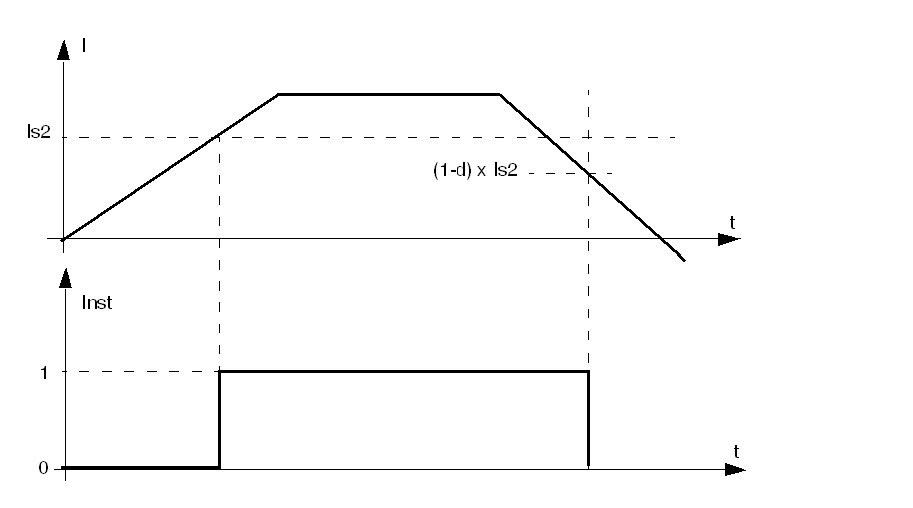
Motor Protection Characteristics
Operation
The following diagram describes the operation of a typical motor protection function. This diagram, and the following diagrams, are expressed in terms of current. However, the same principles apply to voltage.
I Measurement of the monitored parameter
Is1 Alarm threshold setting
Is2 Trip threshold setting
T Trip timeout setting
Inst Instantaneous alarm/trip detection
Settings
Some protection functions include configurable settings, including:
-
Trip threshold: A limit setting for the monitored parameter that triggers a protection function trip.
-
Alarm threshold: A limit setting for the monitored parameter that triggers a protection function alarm.
-
Trip timeout: A time delay that must expire before the protection function trip is triggered. The behavior of a timeout depends on its trip current characteristic profile.
-
Trip curve characteristic (TCC): The LTMR controller includes a definite trip characteristic for all protection functions, except the Thermal Overload Inverse Thermal protection function, which has both an inverse trip and definite trip curve characteristic, as described in the following diagram.

Inverse TCC: The duration of the time delay varies inversely with the value of the measured quantity (here, thermal capacity). As the measured quantity increases, the potential for harm also increases, thereby causing the duration of the time delay to decrease, as described in the following diagram:

Hysteresis
To improve stability, motor protection functions apply a hysteresis value that is added to or subtracted from limit threshold settings before a trip or alarm response is reset. The hysteresis value is calculated as a percentage, typically 5%, of the limit threshold and is
-
Subtracted from the threshold value for upper limit thresholds,
-
Added to the threshold value for lower limit thresholds.
Thermal Motor Protection Functions
Thermal Overload
Overview
The LTMR controller can be configured to provide thermal protection, by selecting one of the following settings:
-
Inverse Thermal (factory setting)
Each setting represents a Trip Curve Characteristic. The LTMR controller stores the selected setting in its Thermal Overload Mode parameter. Only one setting can be activated at a time. See the topics that immediately follow, for information on the operation and configuration of each setting.
Parameter Settings
The Thermal Overload function has the following configurable parameter settings, which apply to every trip current characteristic:
|
Parameters |
Setting Range |
Factory Setting |
|---|---|---|
|
Mode |
|
Inverse thermal |
|
Trip enable |
Enable/Disable |
Enable |
|
Alarm enable |
Enable/Disable |
Enable |
|
Motor auxiliary fan cooled |
Enable/Disable |
Disable |
Thermal Overload - Inverse Thermal
Description
When you set the Thermal Overload Mode parameter to Inverse Thermal and select a motor trip class, the LTMR controller monitors the motor’s utilized thermal capacity and signals
-
An alarm when utilized thermal capacity exceeds a configured alarm threshold,
-
A trip when utilized thermal capacity is greater than 100%.
 CAUTION CAUTION |
|---|
|
RISK OF MOTOR OVERHEATING
The Motor Trip Class parameter must be set to the thermal
heating characteristics of the motor. Refer to the motor manufacturer’s
instructions before setting this parameter.
Failure to follow these instructions can result in injury or equipment damage.
|
There is no time delay for the thermal overload alarm.
The LTMR controller calculates the Thermal Capacity Level in all operating states. When power to the LTMR controller is lost, the LTMR controller retains the last measurements of the motor’s thermal state for 30 minutes, allowing it to estimate the motor’s thermal state when power is reapplied.
Trip and alarm monitoring can be separately enabled and disabled.
-
The thermal overload alarm is cleared by the LTMR controller when the utilized thermal capacity falls 5% below the alarm threshold.
-
The thermal overload trip can be reset when the utilized thermal capacity falls below the trip reset threshold and after the trip reset timeout is elapsed.
Reset for Emergency Restart
You can use the Clear Thermal Capacity Level Command, issued from the PLC or an HMI, to restart an overloaded motor in an emergency situation. This command resets the thermal capacity utilization value to 0 and bypasses the cooling period required by the thermal model before the motor can be restarted.
This command also resets the Rapid Cycle Lockout Timeout to allow an immediate restart without lock.
The Clear All Command does not perform a Clear Thermal Capacity Level.
 WARNING WARNING |
|---|
|
LOSS OF MOTOR PROTECTION
Clearing the thermal capacity level inhibits thermal protection
and can cause equipment overheating and fire. Continued operation
with inhibited thermal protection should be limited to applications
where immediate restart is vital.
Failure to follow these instructions can result in death, serious injury, or equipment
damage.
|
The Clear Thermal Capacity Level Command will not reset the trip response. Instead
-
Only an action external to the LTMR controller (for example, a reduction in the motor load) can clear the trip condition,
-
Only a reset command, from the valid reset means configured in the Trip Reset Mode parameter, will reset the trip response.
| WARNING |
|---|
|
UNINTENDED EQUIPMENT OPERATION
Failure to follow these instructions can result in death, serious injury, or equipment
damage.
|
Operation
The thermal overload inverse thermal protection function is based on a thermal model of the motor that combines two thermal images:
-
A copper-based image representing the thermal state of the stator and rotor windings, and
-
An iron-based image representing the thermal state of the motor frame.
Using measured current and the input motor trip class setting, the LTMR controller considers only the highest thermal state, iron, or copper, when calculating thermal capacity utilized by the motor, as described in the following diagram:
θ Thermal value
θfe Iron tripping threshold
θcu Copper tripping threshold
t Time
When inverse thermal trip mode is selected, the Thermal Capacity Level parameter, indicating utilized thermal capacity due to load current, is incremented during both start and run states. When the LTMR controller detects that the thermal capacity level (θ) exceeds the trip threshold (θ s), it triggers a thermal overload trip, as described in the following diagram:
Functional Characteristics
The Thermal Overload inverse thermal functions include the following features:
-
One motor trip class setting:
-
Motor Trip Class
-
-
Four configurable thresholds:
-
Motor Full Load Current Ratio (FLC1)
-
Motor High-Speed Full Load Current Ratio (FLC2)
-
Thermal Overload Alarm Threshold
-
Thermal Overload Trip Reset Threshold
-
-
One time delay:
-
Trip Reset Timeout
-
-
Two function outputs:
-
Thermal Overload Trip
-
Thermal Overload Trip
-
-
Two counting statistics:
-
Thermal Overload Trips Count
-
Thermal Overload Alarms Count
-
-
One setting for an external auxiliary motor cooling fan:
-
Motor Aux Fan Cooled
-
-
One measure of utilized thermal capacity:
-
Thermal Capacity Level
-
Block Diagram
Imax Maximum current
θmax Thermal capacity level
θs1 Thermal overload alarm threshold
Parameter Settings
The thermal overload inverse thermal functions have the following configurable parameter settings:
|
Parameters |
Setting Range |
Factory Setting |
|---|---|---|
|
FLC1, FLC2 |
|
|
|
Alarm threshold |
10...100 % of thermal capacity |
85 % of thermal capacity |
|
Motor trip class |
5...30 in increments of 5 |
5 |
|
Trip reset timeout |
50...9999 in 1 s increments |
480 s |
|
Trip reset threshold |
35...95 % of thermal capacity |
75% of thermal capacity |
The thermal overload inverse thermal functions have the following non-configurable parameter settings:
|
Parameter |
Fixed Setting |
|---|---|
|
Thermal overload trip threshold |
100% of thermal capacity |
Technical Characteristics
The thermal overload inverse thermal functions have the following characteristics:
|
Characteristics |
Value |
|---|---|
|
Hysteresis |
–5 % of thermal overload alarm threshold |
|
Trip time accuracy |
+/– 0.1 s |
Thermal Overload - Definite Time
Description
When you set the Thermal Overload Mode parameter to Definite Time, the LTMR controller signals:
-
An alarm when measured maximum phase current exceeds a configurable threshold (OC1 or OC2).
-
A trip when the maximum phase current continuously exceeds the same threshold (OC1 or OC2) for a set time delay.
The thermal overload definite time trip includes a time delay of constant magnitude, following a start command, before the protection is active and a trip timeout duration, as described in the following diagram:
IsTrip and alarm threshold (OC1 or OC2)
T1 Start command
T2 Elapsed time delay
There is no time delay for the thermal overload definite time alarm.
Trip and alarm monitoring can be separately enabled and disabled.
The definite time protection function is disabled following a start by a delay defined by the Long Start Trip Timeout setting. The LTMR controller, when configured for overload predefined operating mode, uses the change in state from off to on level current to begin the Start state. This delay allows the motor to draw current on startup required to overcome the inertia of the motor at rest.
Functional Characteristics
The thermal overload definite time function includes the following features:
-
Two configurable threshold settings; one setting (OC1) is used for single speed motors, both settings are required for two-speed motors:
-
OC1(Motor Full Load Current Ratio) or
-
OC2 (Motor High-Speed Full Load Current Ratio)
-
-
One time delay:
-
Overcurrent Time (O-Time, set by the Thermal Overload Trip Definite Timeout parameter)
-
-
Two function outputs:
-
Thermal Overload Alarm
-
Thermal Overload Trip
-
-
Two counting statistics:
-
Thermal Overload Trips Count
-
Thermal Overload Alarms Count
-
Block Diagram
I1 Phase 1 current
I2 Phase 2 current
I3 Phase 3 current
Is Trip and alarm threshold (OC1 or OC2)
T Trip timeout
Parameter Settings
The definite time thermal overload function has the following configurable parameter settings:
|
Parameters |
Setting Range |
Factory Setting |
|---|---|---|
|
Trip threshold:
|
5...100% of FLCmax, in 1% increments. Note: OC1 and OC2 settings can be set directly (in Amperes) in the menu of an HMI, or in the tab of the TeSys T DTM. |
5% FLCmax |
|
Thermal overload trip definite timeout (O-time or over-current time) |
1...300 s in 1 s increments |
10 s |
|
Thermal overload alarm threshold |
20...800% of OC in 1% increments |
80% of OC |
|
Long start trip timeout* (D-time) |
1...200 s in 1 s increments |
10 s |
Technical Characteristics
The definite time thermal overload function has the following characteristics:
|
Characteristics |
Value |
|---|---|
|
Hysteresis |
–5% of alarm and trip thresholds |
|
Trip time accuracy |
+/– 0.1 s |
Example
The following diagram describes a definite time thermal overload trip:
OC Trip threshold (OC1 or OC2)
Motor Temperature Sensor
Overview
The LTMR controller has two terminals, T1 and T2 that can be connected to a motor temperature sensing element to provide protection for motor windings by detecting high temperature conditions that could lead to damage or degradation.
These protections are activated when the Motor Temp Sensor Type parameter is set to one of the following settings:
Only one of these motor protection sensing elements can be enabled at a time.
When a sensor type is changed, the LTMR controller’s motor temperature sensing configuration settings revert to their factory settings. If a sensor type is replaced with another sensor of the same type, the setting values are retained.
Parameter Settings
The motor temperature sensor function has the following configurable parameter settings, which apply to the selected motor temp sensor type:
|
Parameters |
Setting Range |
Factory Setting |
|---|---|---|
|
Sensor type |
|
None |
|
Trip enable |
Enable/Disable |
Disable |
|
Alarm enable |
Enable/Disable |
Disable |
Motor Temperature Sensor - PTC Binary
Description
The PTC Binary motor temperature sensing function is enabled when the Motor Temp Sensor Type parameter is set to PTC Binary and the LTMR controller is connected to a binary positive temperature coefficient thermistor embedded in the motor.
The LTMR controller monitors the state of the temperature sensing element and signals:
-
A motor temperature sensor alarm when the measured resistance exceeds a fixed threshold.
-
A motor temperature sensor trip when the measured resistance exceeds the same fixed threshold.
The trip and alarm conditions continue until measured resistance falls below a separate fixed motor temperature sensor reclosing threshold.
Motor temperature sensing trip thresholds are factory pre-set and are not configurable. Trip monitoring can be enabled or disabled.
The function is available for all operating states.
Functional Characteristics
The PTC Binary motor temperature sensor function includes the following features:
-
Two function output:
-
Motor Temp Sensor Alarm
-
Motor Temp Sensor Trip
-
-
One counting statistic:
-
Motor Temp Sensor Trips Count
-
Block Diagram
θ Temperature sensing element resistance
Parameter Settings
The PTC binary motor temperature sensor function has the following non-configurable parameter settings:
|
Parameter |
Fixed settings |
Accuracy |
|---|---|---|
|
Trip/Alarm threshold |
2900 Ω |
+/– 2% |
|
Trip/Alarm reclosing threshold |
1575 Ω |
+/– 2% |
Technical Characteristics
The PTC binary motor temperature sensor function has the following characteristics:
|
Characteristic |
Value |
|---|---|
|
Detection time |
0.5...0.6 s |
|
Detection time accuracy |
+/– 0.1 s |
Example
The following diagram describes the occurrence of a PTC binary motor temp sensor trip with an automatic reset:
2900 Ω Trip threshold
1575 Ω Trip reclosing threshold
Reset This marks the time after which a reset can be executed. A start command is required before run state can be resumed. In this example, auto-reset has been enabled.
Motor Temperature Sensor - PT100
Description
The PT100 motor temperature sensing function is enabled when the Motor Temperature Sensor Type parameter is set to PT100 and the LTMR controller is connected to a PT100 sensor embedded in the motor.
The LTMR controller monitors the state of the temperature sensing element and signals:
-
A motor temperature sensor alarm when the measured temperature exceeds a configurable alarm threshold.
-
A motor temperature sensor trip when the measured temperature exceeds a separately set trip threshold.
The LTMR directly measures the temperature with a PT100 sensor. The temperature measured by the PT100 sensor, either in °C (factory setting) or in °F, is displayed on the HMI or the TeSys T DTM, according to the Motor Temperature Sensor Display Degree CF parameter:
The trip or alarm condition continues until the measured temperature falls below 95% of the trip or alarm threshold.
There is a fixed detection time of 0.5 s to 0.6 s to the motor temperature sensor trip or alarm.
Trip and alarm monitoring can be separately enabled and disabled.
The function is available for all operating states.
The temperature is derived from the following equation: T = 2.6042 * R - 260.42,
Where R = resistance Ω).
Functional Characteristics
The PT100 motor temperature sensor function includes the following features:
-
Two configurable thresholds:
-
Motor Temperature Sensor Alarm Threshold Degree
-
Motor Temperature Sensor Trip Threshold Degree
-
-
Two function outputs:
-
Motor Temperature Sensor Alarm
-
Motor Temperature Sensor Trip
-
-
One counting statistic:
-
Motor Temperature Sensor Trips Count
-
-
One display configuration:
-
Motor Temperature Sensor Display Degree CF
-
Block Diagram
θ Temperature measured by the PT100 sensor
θs1 Motor temperature sensor alarm threshold
θs2 Motor temperature sensor trip threshold
Parameter Settings
The PT100 motor temperature sensor function has the following configurable parameter settings:
|
Parameters |
Setting Range |
Factory Setting |
|---|---|---|
|
Trip threshold degree |
0...200 °C in 1 °C increments |
0 °C |
|
Alarm threshold degree |
0...200 °C in 1 °C increments |
0 °C |
|
Motor temperature sensor display degree CF |
°C (0) °F (1) |
°C |
Technical Characteristics
The PT100 motor temperature sensor function has the following characteristics:
|
Characteristic |
Value |
|---|---|
|
Hysteresis |
–5% of Alarm threshold and Trip threshold |
|
Detection time |
0.5...0.6 s |
|
Trip time accuracy |
+/– 0.1 s |
Example
The following diagram describes a Motor temperature sensor PT100 trip with automatic reset and an active Run command:
θs2 Trip threshold
θs3 Trip reclosing threshold (95% of trip threshold)
Motor Temperature Sensor - PTC Analog
Description
The PTC Analog motor temperature sensing function is enabled when the Motor Temp Sensor Type parameter is set to PTC Analog and the LTMR controller is connected to an analog PTC thermistor embedded in the motor.
The LTMR controller monitors the state of the temperature sensing element and signals:
-
A motor temperature sensor alarm when the measured resistance exceeds a configurable alarm threshold.
-
A motor temperature sensor trip when the measured resistance exceeds a separately set trip threshold.
The trip or alarm condition continues until the measured resistance falls below 95% of the trip or alarm threshold.
Trip and alarm monitoring can be separately enabled and disabled.
The function is available for all operating states.
Functional Characteristics
The PTC Analog motor temperature sensor function includes the following features:
-
Two configurable thresholds:
-
Motor Temp Sensor Alarm Threshold
-
Motor Temp Sensor Trip Threshold
-
-
Two function outputs:
-
Motor Temp Sensor Alarm
-
Motor Temp Sensor Trip
-
-
One counting statistic:
-
Motor Temp Sensor Trips Count
-
Block Diagram
θ Temperature sensing element resistance
θs1 Motor temperature sensor alarm threshold
θs2 Motor temperature sensor trip threshold
Parameter Settings
The PTC analog motor temperature sensor function has the following configurable parameter settings:
|
Parameters |
Setting Range |
Factory Setting |
|---|---|---|
|
Trip threshold |
20...6500 Ω in 0.1 Ω increments |
20 Ω |
|
Alarm threshold |
20...6500 Ω in 0.1 Ω increments |
20 Ω |
Technical Characteristics
The PTC analog motor temperature sensor function has the following characteristics:
|
Characteristic |
Value |
|---|---|
|
Hysteresis |
– 5% of Alarm threshold and Trip threshold |
|
Detection time |
0.5...0.6 s |
|
Detection time accuracy |
+/– 0.1 s |
Example
The following diagram describes a Motor temperature sensor PTC analog trip with automatic reset and an active Run command:
θs2 Trip threshold
θs3 Trip reclosing threshold (95% of trip threshold)
Motor Temperature Sensor - NTC Analog
Description
The NTC Analog motor temperature sensing function is enabled when the Motor Temp Sensor Type parameter is set to NTC Analog and the LTMR controller is connected to an analog NTC thermistor embedded in the motor.
The LTMR controller monitors the state of the temperature sensing element and signals:
-
A motor temperature sensor alarm when the measured resistance falls below a configurable alarm threshold.
-
A motor temperature sensor trip when the measured resistance falls below a separately set trip threshold.
The trip or alarm condition continues until the measured resistance exceeds 105% of the trip or alarm threshold.
Trip and alarm monitoring can be separately enabled and disabled.
The function is available for all operating states.
Functional Characteristics
The NTC Analog motor temperature sensor function includes the following features:
-
Two configurable thresholds:
-
Alarm Threshold
-
Trip Threshold
-
-
Two function outputs:
-
Motor Temp Sensor Alarm
-
Motor Temp Sensor Trip
-
-
One counting statistic:
-
Motor Temp Sensor Trips Count
-
Block Diagram
θ Temperature sensing element resistance
θs1 Motor temperature sensor alarm threshold
θs2 Motor temperature sensor trip threshold
Parameter Settings
The NTC analog motor temperature sensor function has the following configurable parameter settings:
|
Parameters |
Setting Range |
Factory Setting |
|---|---|---|
|
Trip threshold |
20...6500 Ω in 0.1 Ω increments |
20 Ω |
|
Alarm threshold |
20...6500 Ω in 0.1 Ω increments |
20 Ω |
Technical Characteristics
The NTC analog motor temperature sensor function has the following characteristics:
|
Characteristics |
Value |
|---|---|
|
Hysteresis |
+ 5% of Alarm threshold and Trip thresholds |
|
Detection time |
0.5...0.6 s |
|
Detection time accuracy |
+/– 0.1 s |
Example
The following diagram describes a Motor temperature sensor NTC analog trip with automatic reset:
θr2 Trip threshold
θr3 Trip reclosing threshold (105% of trip threshold)
Rapid Cycle Lockout
Description
The rapid cycle lockout function prevents potential harm to the motor caused by repetitive, successive inrush currents resulting from too little time between starts.
The rapid cycle lockout function provides a configurable timer, which begins its count when the LTMR controller detects On Level Current–defined as 20% of FLC. At the same time, the Rapid Cycle Lockout bit is set.
If the LTMR controller detects a Run command before the rapid cycle lockout has elapsed, the:
-
Rapid Cycle Lockout bit remains set
-
LTMR controller ignores the Run command. It prevents the motor from restarting
-
HMI device (if attached) displays "WAIT"
-
LTMR controller Alarm LED flashes red 5 times per second, indicating the LTMR controller has disabled motor outputs thereby preventing an undesirable condition caused by starting the motor
-
LTMR controller monitors the wait time-if more than one timer is active, the LTMR controller reports the minimum wait time before the longest timer elapses
On power loss, the LTMR controller stores the state of the lockout timer in non-volatile memory. When the LTMR controller next powers up, the timer restarts its count and again ignores Run commands until the timer completes the timeout.
Setting the Rapid Cycle Lockout Timeout parameter to 0 disables this function.
The Rapid Cycle Lockout Timeout setting can be edited when the LTMR controller is in its normal operating state. If an edit is made while the timer is counting, the edit is effective when the timer finishes counting.
This function has no alarm and no trip.
Functional Characteristics
The rapid cycle lockout function includes the following parameters:
-
One time delay:
-
Rapid Cycle Lockout Timeout
-
-
One status bit:
-
Rapid Cycle Lockout
-
In addition, the Rapid Cycle Lockout function:
-
Disables motor outputs
-
Causes the LTMR Alarm LED to flash 5 times per second
Parameter Settings
The rapid cycle lockout function has the following parameters:
|
Parameters |
Setting Range |
Factory Setting |
|---|---|---|
|
Rapid cycle lockout timeout |
0...9999 s in increments of 1 s |
0 s |
Technical Characteristics
The rapid cycle lockout function has the following characteristics:
|
Characteristics |
Value |
|---|---|
|
Trip time accuracy |
+/– 0.1 s or +/– 5% |
Example

Current Motor Protection Functions
Current Phase Imbalance
Description
The current phase imbalance function signals:
-
An alarm when the current in any phase differs by more than a set percentage from the average current in all three phases.
-
A trip when the current in any phase differs by more than a separately set percentage from the average current in all three phases for a set period of time.
| CAUTION |
|---|
|
RISK OF MOTOR OVERHEATING
Failure to follow these instructions can result in injury or equipment damage.
|
This function has two adjustable trip time delays:
-
One applies to current imbalances occurring while the motor is in start state, and
-
One applies to current imbalances occurring after startup while the motor is in run state
Both timers begin if the imbalance is detected in start state.
The function identifies the phase causing a current imbalance. If the maximum deviation from the three-phase current average is the same for two phases, the function identifies both phases.
Trip and alarm monitoring can be separately enabled and disabled.
The function applies only to three-phase motors.
Functional Characteristics
The current phase imbalance function includes the following features:
-
Two thresholds:
-
Alarm Threshold
-
Trip Threshold
-
-
Two trip time delays:
-
Trip Timeout Starting
-
Trip Timeout Running
-
-
Two function outputs:
-
Current Phase Imbalance Alarm
-
Current Phase Imbalance Trip
-
-
One counting statistic:
-
Current Phase Imbalance Trips Count
-
-
Three indicators identifying the phase or phases with the highest current imbalance:
-
L1 Current Highest Imbalance
-
L2 Current Highest Imbalance
-
L3 Current Highest Imbalance
-
Block Diagram
Current phase imbalance alarm and trip:
I1 Phase 1 current
I2 Phase 2 current
I3 Phase 3 current
Iimb Current imbalance ratio for three-phase
Is1 Alarm threshold
Is2 Trip threshold
T1 Trip timeout starting
T2 Trip timeout running
Parameter Settings
The current phase imbalance function has the following parameters:
|
Parameters |
Setting Range |
Factory Setting |
|---|---|---|
|
Trip enable |
Enable/Disable |
Enable |
|
Trip timeout starting |
0.2...20 s in 0.1 s increments |
0.7 s |
|
Trip timeout running |
0.2...20 s in 0.1 s increments |
5 s |
|
Trip threshold |
10...70% of the calculated imbalance in 1% increments |
10% |
|
Alarm enable |
Enable/Disable |
Disable |
|
Alarm threshold |
10...70% of the calculated imbalance in 1% increments |
10% |
Technical Characteristics
The current phase imbalance function has the following characteristics:
|
Characteristics |
Value |
|---|---|
|
Hysteresis |
– 5% of trip or alarm threshold |
|
Trip time accuracy |
+/– 0.1 s or +/– 5% |
Example
The following diagram describes the detection of a current phase imbalance occurring during run state.
ΔI Percentage difference between current in any phase and the three-phase current average
Is2 Trip threshold
Current Phase Loss
Description
The current phase loss function signals:
-
An alarm when the current in any phase differs by more than 80% from the average current in all three phases.
-
A trip when the current in any phase differs by more than 80% from the average current in all three phases for a set period of time.
This function has a single adjustable trip time delay, which is applied when the motor is in start state or run state.
The function identifies the phase experiencing a current loss. If the maximum deviation from the three-phase current average is the same for two phases, the function identifies both phases.
Trip and alarm monitoring can be separately enabled and disabled.
The function applies only to three-phase motors.
Functional Characteristics
The current phase loss function includes the following features:
-
One fixed trip and alarm threshold equal to 80% of the three-phase average current.
-
One trip time delay:
-
Current Phase Loss Timeout
-
-
Two function outputs:
-
Current Phase Loss Alarm
-
Current Phase Loss Trip
-
-
One counting statistic:
-
Current Phase Loss Trips Count
-
-
Three indicators identifying the phase or phases experiencing the current loss:
-
L1 Current loss
-
L2 Current loss
-
L3 Current loss
-
Block Diagram
I1 Phase 1 current
I2 Phase 2 current
I3 Phase 3 current
Ln Line current number or numbers with the greatest deviation from Iavg
Iavg three-phase current average
T Trip timeout
Parameter Settings
The current phase loss function has the following configurable parameters:
|
Parameters |
Setting Range |
Factory Setting |
|---|---|---|
|
Trip enable |
Enable/Disable |
Enable |
|
Timeout |
0.1...30 s in 0.1 s increments |
3 s |
|
Alarm enable |
Enable/Disable |
Enable |
Technical Characteristics
The current phase loss function has the following characteristics:
|
Characteristics |
Value |
|---|---|
|
Hysteresis |
75% of the three-phase average current |
|
Trip time accuracy |
+/– 0.1 s or +/– 5% |
Example
The following diagram describes the occurrence of a current phase loss trip of a motor in run state.
Δ%I Percentage difference between current in any phase and the three-phase current average
Current Phase Reversal
Description
The current phase reversal function signals a trip when it detects that the current phases of a three-phase motor are out of sequence with the Motor Phases Sequence parameter, ABC, or ACB.
This function:
-
Is active when the motor is in start state or run state
-
Applies only to three-phase motors
-
Has no alarm and no timer.
This function can be enabled or disabled.
Functional Characteristics
The current phase reversal function adds to one counting statistic, Wiring Trips Count.
Parameter Settings
The current phase reversal function has the following configurable parameters:
|
Parameters |
Setting Range |
Factory Setting |
|---|---|---|
|
Trip enable |
Enable/Disable |
Disable |
|
Phase sequence |
|
A-B-C |
Technical Characteristics
The current phase reversal function has the following characteristics:
|
Characteristic |
Value |
|---|---|
|
Trip time at motor startup |
Within 0.2 s of motor startup |
|
Trip time accuracy |
+/– 0.1 s or +/– 5% |
Long Start
Description
The long start function detects a locked or stalled rotor in start state and signals a trip when current continuously exceeds a separately set threshold for the same period of time.
Each predefined operating mode has its own current profile, representing a successful start cycle for the motor. The LTMR controller detects a long start trip condition whenever the actual current profile, occurring after a start command, varies from the expected profile.
Trip monitoring can be separately enabled and disabled.
This function has no alarm.
Start Cycle
The configurable parameters for the Long Start protection function, Long Start Trip Threshold, and Long Start Trip Timeout, are used by the LTMR controller in defining and detecting the motor’s start cycle. For more information, refer to Start Cycle.
Functional Characteristics
The long start function includes the following features:
-
One threshold:
-
Trip Threshold
-
-
One trip time delay:
-
Trip Timeout
-
-
One function outputs:
-
Long Start Trip
-
-
One counting statistic:
-
Long Start Trips Count
-
Block Diagram
I1 Phase 1 current
I2 Phase 2 current
I3 Phase 3 current
Is2 Trip threshold
T Trip timeout
Parameter Settings
The long start function has the following parameters:
|
Parameters |
Setting Range |
Factory Setting |
|---|---|---|
|
Trip enable |
Enable/Disable |
Enable |
|
Trip timeout |
1...200 s in 1 s increments |
10 s |
|
Trip threshold |
100...800% of FLC |
100% of FLC |
Technical Characteristics
The long start function has the following characteristics:
|
Characteristic |
Value |
|---|---|
|
Hysteresis |
– 5% of Trip threshold |
|
Trip time accuracy |
+/– 0.1 s or +/– 5% |
Example
The following diagram describes the occurrence of a single threshold cross long start trip:
Is2 Long start trip threshold
Jam
Description
The jam function detects a locked rotor during run state and signals:
-
An alarm when current in any phase exceeds a set threshold after the motor has reached run state.
-
A trip when current in any phase continuously exceeds a separately set threshold for a specified period of time after the motor has reached run state.
The jam function is triggered when the motor is jammed during run state and stops, or is suddenly overloaded and draws excessive current.
Trip and alarm monitoring can be separately enabled and disabled.
Functional Characteristics
The jam function includes the following features:
-
Two thresholds:
-
Alarm Threshold
-
Trip Threshold
-
-
One trip time delay:
-
Trip Timeout
-
-
Two function outputs:
-
Jam Alarm
-
Jam Trip
-
-
One counting statistic:
-
Jam Trips Count
-
Block Diagram
Jam alarm and trip:
I1 Phase 1 current
I2 Phase 2 current
I3 Phase 3 current
Is1 Alarm threshold
Is2 Trip threshold
T Trip timeout
Parameter Settings
The jam function has the following parameters:
|
Parameters |
Setting Range |
Factory Setting |
|---|---|---|
|
Trip enable |
Enable/Disable |
Enable |
|
Trip timeout |
1...30 s in 1 s increments |
5 s |
|
Trip threshold |
100...800% of FLC in 1% increments |
200% of FLC |
|
Alarm enable |
Enable/Disable |
Disable |
|
Alarm threshold |
100...800% of FLC in 1% increments |
200% of FLC |
Technical Characteristics
The jam function has the following characteristics:
|
Characteristics |
Value |
|---|---|
|
Hysteresis |
– 5% of Trip threshold or Alarm threshold |
|
Trip time accuracy |
+/– 0.1 s or +/– 5% |
Example
The following diagram describes the occurrence of a jam trip.
Is2 Jam trip threshold
Undercurrent
Description
The undercurrent function signals:
-
An alarm when the three-phase Average Current falls below a set threshold after the motor has reached run state.
-
A trip when the three-phase Average Current falls and remains below a separately set threshold for a set period of time after the motor has reached run state.
The undercurrent function is triggered when the motor current falls below a defined level for the driven load, for example, if a drive belt or shaft has broken, allowing the motor to run free rather than under load. This function has a single trip time delay. Trip and alarm monitoring can be separately enabled and disabled.
Functional Characteristics
The undercurrent function includes the following features:
-
Two thresholds:
-
Alarm Threshold
-
Trip Threshold
-
-
One trip time delay:
-
Trip Timeout
-
-
Two function outputs:
-
Undercurrent Alarm
-
Undercurrent Trip
-
-
One counting statistic:
-
Undercurrent Trips Count
-
Block Diagram
Undercurrent alarm and trip:

Iavg Average current
Is1 Alarm threshold
Is2 Trip threshold
T Trip timer delay
Parameter Settings
The undercurrent function has the following parameters:
|
Parameters |
Setting Range |
Factory Setting |
|---|---|---|
|
Trip enable |
Enable/Disable |
Disable |
|
Trip timeout |
1...200 s in 1 s increments |
1 s |
|
Trip threshold |
30...100% of FLC in 1% increments |
50% of FLC |
|
Alarm enable |
Enable/Disable |
Disable |
|
Alarm threshold |
30...100% of FLC in 1% increments |
50% of FLC |
Technical Characteristics
The undercurrent function has the following characteristics:
|
Characteristics |
Value |
|---|---|
|
Hysteresis |
– 5% of Trip threshold or Alarm threshold |
|
Trip time accuracy |
+/– 0.1 s or +/– 5% |
Example
The following diagram describes the occurrence of an undercurrent trip.
Is2 Undercurrent trip threshold
Overcurrent
Description
The overcurrent function signals:
-
An alarm when current in a phase exceeds a set threshold after the motor has reached run state.
-
A trip when current in a phase continuously exceeds a separately set threshold for a set period of time after the motor has reached run state.
The overcurrent function can be triggered when the equipment is overloaded or a process condition is detected causing current to increase beyond the set threshold. This function has a single trip time delay. Trip and alarm monitoring can be separately enabled and disabled.
Functional Characteristics
The overcurrent function includes the following features:
-
Two thresholds:
-
Alarm Threshold
-
Trip Threshold
-
-
One trip time delay:
-
Trip Timeout
-
-
Two function outputs:
-
Overcurrent Alarm
-
Overcurrent Trip
-
-
One counting statistic:
-
Overcurrent Trips Count
-
Block Diagram
I1 Phase 1 current
I2 Phase 2 current
I3 Phase 3 current
Is1 Alarm threshold
Is2 Trip threshold
T Trip timeout
Parameter Settings
The overcurrent function has the following parameters:
|
Parameters |
Setting Range |
Factory Setting |
|---|---|---|
|
Trip enable |
Enable/Disable |
Disable |
|
Trip timeout |
1...250 s in 1 s increments |
10 s |
|
Trip threshold |
30...800% of FLC in 1% increments |
200% of FLC |
|
Alarm enable |
Enable/Disable |
Disable |
|
Alarm threshold |
30...800% of FLC in 1% increments |
200% of FLC |
Technical Characteristics
The overcurrent function has the following characteristics:
|
Characteristics |
Value |
|---|---|
|
Hysteresis |
– 5% of Trip threshold or Alarm threshold |
|
Trip time accuracy |
+/– 0.1 s or +/– 5% |
Example
The following diagram describes the occurrence of an overcurrent trip.
Is2 Overcurrent trip threshold
Ground Current
Overview
The LTMR controller can be configured to detect ground current:
-
Internally, by summing the three-phase current signals from the secondary of the internal current transformers.
-
Externally, by measuring the current delivered by the secondary of an external ground current sensor.
Use the Ground Current Mode parameter to select either internal or external ground current trip protection. Only one of these ground current mode settings can be activated at a time.
Parameter Settings
The ground current protection function has the following configurable parameter settings, which apply to both internal and external ground current protection:
|
Parameters |
Setting Range |
Factory Setting |
|---|---|---|
|
Ground current mode |
|
Internal |
|
Trip enable |
Enable/Disable |
Enable |
|
Alarm enable |
Enable/Disable |
Enable |
|
Ground current trip disabled while starting |
Enable/Disable |
Enable |
Internal Ground Current
Description
The internal ground current function is enabled when the Ground Current Mode parameter is set to Internal and disabled when set to External.
 DANGER DANGER |
|---|
|
IMPROPER TRIP DETECTION
Failure to follow these instructions will result in death or serious injury.
|
The internal ground current function sums the current readings from the secondary of the internal current transformers and signals:
-
An alarm when the summed current exceeds a set threshold.
-
A trip when the summed current continuously exceeds a separately set threshold for a set period of time.
The internal ground current function has a single trip time delay.
The internal ground current function can be enabled when the motor is in ready state, start state, or run state. This function can be configured so that it is disabled during start state, and enabled only during ready state and run state.
Trip and alarm monitoring can be separately enabled and disabled.
Functional Characteristics
The internal ground current function includes the following features:
-
One measure of ground current in amperes:
-
Ground Current
-
-
One measure of ground current as a % of FLCmin:
-
Ground Current Ratio
-
-
Two thresholds:
-
Alarm Threshold
-
Trip Threshold
-
-
One trip time delay:
-
Trip Timeout
-
-
Two function outputs:
-
Internal Ground Current Alarm
-
Internal Ground Current Trip
-
-
One counting statistic:
-
Ground Current Trips Count
-
Block Diagram
I1 Phase 1 current
I2 Phase 2 current
I3 Phase 3 current
IΣ Summed current
IΣs1 Alarm threshold
IΣs2 Trip threshold
T Trip timeout
Parameter Settings
The internal ground current function has the following parameters:
|
Parameters |
Setting Range |
Factory Setting |
|---|---|---|
|
Internal ground current trip timeout |
0.5...25 s in 0.1 s increments |
1 s |
|
Internal ground current trip threshold |
50...500% of FLCmin in 1% increments |
50% of FLCmin |
|
Internal ground current alarm threshold |
50...500% of FLCmin in 1% increments |
50% of FLCmin |
Technical Characteristics
The internal ground current function has the following characteristics:
|
Characteristics |
Value |
|---|---|
|
Hysteresis |
– 5% of Trip threshold or Alarm threshold |
|
Trip time accuracy |
+/– 0.1 s or +/– 5% |
Example
The following diagram describes the occurrence of an internal ground current trip occurring during run state.
IΣs2 Internal ground current trip threshold
External Ground Current
Description
The external ground current function is enabled when:
-
The Ground Current Mode parameter is set to External, and
-
A current transformation ratio is set.
When Ground Current Mode is set to Internal, the external ground current function is disabled.
| DANGER |
|---|
|
IMPROPER TRIP DETECTION
Failure to follow these instructions will result in death or serious injury.
|
The LTMR controller has two terminals-Z1 and Z2-that can be connected to an external ground current sensor. The external ground current function measures ground current delivered by the secondary of the external current transformer and signals:
-
An alarm when the delivered current exceeds a set threshold.
-
A trip when the delivered current continuously exceeds a separately set threshold for a set period of time.
The external ground current function has a single trip time delay.
The external ground current function can be enabled when the motor is in ready state, start state, or run state. This function can be configured so that it is disabled only during start state, and enabled during ready state and run state.
Trip and alarm monitoring can be separately enabled and disabled.
Functional Characteristics
The external ground current function includes the following features:
-
One measure of ground current in amperes:
-
Ground Current
-
-
Two thresholds:
-
Alarm Threshold
-
Trip Threshold
-
-
One trip time delay:
-
Trip Timeout
-
-
Two function outputs:
-
External Ground Current Alarm
-
External Ground Current Trip
-
-
One counting statistic:
-
Ground Current Trips Count
-
Block Diagram
Igr Ground current from external ground CT
Igr s1 Alarm threshold
Igr s2 Trip threshold
T Trip timeout
Parameter Settings
The external ground current function has the following parameters:
|
Parameters |
Setting Range |
Factory Setting |
|---|---|---|
|
External ground current trip timeout |
0.1...25 s in 0.01 s increments |
0.5 s |
|
External ground current trip threshold |
0.02...20 A in 0.01 A increments |
1 A |
|
External ground current alarm threshold |
0.02...20 A in 0.01 A increments |
1 A |
Technical Characteristics
The external ground current function has the following characteristics:
|
Characteristics |
Value |
|---|---|
|
Hysteresis |
– 5% of Trip threshold or Alarm threshold |
|
Trip time accuracy |
+/– 0.1 s or +/– 5% |
Example
The following diagram describes the occurrence of an external ground current trip occurring during run state.
Igr s2 External ground current trip threshold
Voltage Motor Protection Functions
Overview
This section describes the voltage motor protection functions provided by the LTMR controller.
Voltage Phase Imbalance
Description
The voltage phase imbalance function signals:
-
An alarm when the voltage in any composed phase differs by more than a set percentage from the average voltage in all three phases
-
A trip when the voltage in any composed phase differs by more than a separately set percentage from the average voltage in all three phases for a set period of time
This function:
-
Is active when the LTMR controller is connected to an expansion module
-
Is active when the average voltage is between 50% and 120% of the nominal voltage
-
Is available when the motor is in ready state, start state, and run state
-
Applies only to three-phase motors
This function has two adjustable trip time delays:
-
One applies to voltage imbalances occurring while the motor is in start state, and
-
One applies to voltage imbalances occurring while the motor is in run state, or when the long start time duration expires
Both timers begin if the imbalance is detected in start state.
Trip and alarm monitoring can be separately enabled and disabled.
Functional Characteristics
The voltage phase imbalance function includes the following features:
-
Two thresholds:
-
Alarm Threshold
-
Trip Threshold
-
-
Two trip time delays:
-
Trip Timeout Starting
-
Trip Timeout Running
-
-
Two function outputs:
-
Voltage Phase Imbalance Alarm
-
Voltage Phase Imbalance Trip
-
-
One counting statistic:
-
Voltage Phase Imbalance Trips Count
-
-
Three indicators identifying the phase with the highest voltage imbalance:
-
L1-L2 Highest Imbalance
-
L2-L3 Highest Imbalance
-
L3-L1 Highest Imbalance
-
Block Diagram
V1 L1-L2 voltage
V2 L2-L3 voltage
V3 L3-L1 voltage
Ln Line number or numbers with greatest deviation from Vavg
Vs1 Alarm threshold
Vs2 Trip threshold
Vavg Three-phase voltage average
T1 Trip timeout starting
T2 Trip timeout running
Parameter Settings
The voltage phase imbalance function has the following parameters:
|
Parameters |
Setting Range |
Factory Setting |
|---|---|---|
|
Trip enable |
Enable/Disable |
Disable |
|
Trip timeout starting |
0.2...20 s in 0.1 s increments |
0.7 s |
|
Trip timeout running |
0.2...20 s in 0.1 s increments |
2 s |
|
Trip threshold |
3...15% of the calculated imbalance in 1% increments |
10% |
|
Alarm enable |
Enable/Disable |
Disable |
|
Alarm threshold |
3...15% of the calculated imbalance in 1% increments |
10% |
Technical Characteristics
The voltage phase imbalance function has the following characteristics:
|
Characteristics |
Value |
|---|---|
|
Hysteresis |
– 5% of Trip threshold or Alarm threshold |
|
Trip time accuracy |
+/– 0.1 s or +/– 5% |
Example
The following diagram describes the occurrence of a voltage phase imbalance:
V%Δ Percentage difference between voltage in any phase and the three-phase average voltage
Vs2 Trip threshold
Voltage Phase Loss
Description
The voltage phase loss function is based on the Voltage Phase Imbalance function and signals:
-
An alarm when the voltage in any phase differs by more than 32% from the average voltage in all three phases.
-
A trip when the voltage in any phase differs by more than 32% from the average voltage in all three phases for a set period of time.
This function:
-
Is active when the LTMR controller is connected to an expansion module
-
Is active when the average voltage is between 50% and 120% of the nominal voltage
-
Is available when the motor is in ready state or start state
-
Applies only to three-phase motors
This function has a single adjustable trip time delay.
The function identifies the phase experiencing a voltage loss. If the maximum deviation from the three-phase voltage average is the same for two phases, the function identifies both phases.
Trip and alarm monitoring can be separately enabled and disabled.
Functional Characteristics
The voltage phase loss function includes the following features:
-
A fixed trip and alarm threshold equal to 32% of the three-phase average voltage.
-
A single, adjustable trip time delay:
-
Voltage Phase Loss Timeout
-
-
Two function outputs:
-
Voltage Phase Loss Alarm
-
Voltage Phase Loss Trip
-
-
One counting statistic:
-
Voltage Phase Loss Trips Count
-
-
Three indicators identifying the phase experiencing the voltage loss:
-
L1-L2 Voltage loss
-
L2-L3 Voltage loss
-
L3-L1 Voltage loss
-
Block Diagram
V1 L1-L2 voltage
V2 L2-L3 voltage
V3 L3-L1 voltage
Ln Line voltage number or numbers with the greatest deviation from Vavg
Vavg Three-phase average voltage
T Trip timeout
Parameter Settings
The voltage phase loss function has the following configurable parameters:
|
Parameters |
Setting Range |
Factory Setting |
|---|---|---|
|
Trip enable |
Enable/Disable |
Enable |
|
Trip timeout |
0.1...30 s in 0.1 s increments |
3 s |
|
Alarm enable |
Enable/Disable |
Enable |
Technical Characteristics
The voltage phase loss function has the following characteristics:
|
Characteristics |
Value |
|---|---|
|
Hysteresis |
45% of the three-phase average voltage |
|
Trip time accuracy |
+/– 0.1 s or +/– 5% |
Example
The following diagram describes the occurrence of a voltage phase loss trip of a motor in start state:
ΔV% Percentage difference between voltage in any phase and the three-phase average voltage
Voltage Phase Reversal
Description
The voltage phase reversal function signals a trip when it detects that the voltage phases of a three-phase motor are out of sequence, usually indicating a detected wiring error. Use the Motor Phases Sequence parameter to configure the direction, ABC or ACB, in which the motor will turn.
This function:
-
Is available when the LTMR controller is connected to an expansion module
-
Is active when the average voltage is between 50% and 120% of the nominal voltage
-
Is available when the motor is in ready state, start state and run state
-
Applies only to three-phase motors
-
Has no alarm and no timer
This function can be enabled or disabled.
Functional Characteristics
The voltage phase reversal function adds one counting statistic, Wiring Trips Count.
Parameter Settings
The voltage phase reversal function has the following configurable parameters:
|
Parameters |
Setting Range |
Factory Setting |
|---|---|---|
|
Trip enable |
Enable/Disable |
Disable |
|
Motor phases sequence |
|
A-B-C |
Technical Characteristics
The voltage phase reversal function has the following characteristics:
|
Characteristics |
Value |
|---|---|
|
Trip time |
Within 0.2 s |
|
Trip time accuracy |
+/– 0.1 s |
Undervoltage
Description
The undervoltage function signals:
-
An alarm when voltage in a phase falls below a set threshold.
-
A trip when voltage in a phase falls and remains below a separately set threshold for a set period of time.
This function has a single trip time delay. Both the trip and alarm thresholds are defined as a percentage of the Motor Nominal Voltage (Vnom) parameter setting.
The undervoltage function is available only in ready state and run state when the LTMR controller is connected to an expansion module.
Trip and alarm monitoring can be separately enabled and disabled.
Functional Characteristics
The undervoltage function includes the following features:
-
Two thresholds:
-
Alarm Threshold
-
Trip Threshold
-
-
One trip time delay:
-
Trip Timeout
-
-
Two function outputs:
-
Undervoltage Alarm
-
Undervoltage Trip
-
-
One counting statistic:
-
Undervoltage Trips Count
-
Block Diagram
V1 L1-L2 voltage
V2 L2-L3 voltage
V3 L3-L1 voltage
Vs1 Alarm threshold
Vs2 Trip threshold
T Trip timeout
Parameter Settings
The undervoltage function has the following parameters:
|
Parameters |
Setting Range |
Factory Setting |
|---|---|---|
|
Trip enable |
Enable/Disable |
Disable |
|
Trip timeout |
0.2...25 s in 0.1 s increments |
3 s |
|
Trip threshold |
70...99% of Motor nominal voltage in 1% increments |
85% |
|
Alarm enable |
Enable/Disable |
Disable |
|
Alarm threshold |
70...99% of Motor nominal voltage in 1% increments |
85% |
Technical Characteristics
The undervoltage function has the following characteristics:
|
Characteristics |
Value |
|---|---|
|
Hysteresis |
– 5% of Trip threshold or Alarm threshold |
|
Trip time accuracy |
+/– 0.1 s or +/– 5% |
Example
The following diagram describes the occurrence of an undervoltage trip.
Vs2 Undervoltage trip threshold
Overvoltage
Description
The overvoltage function signals:
-
An alarm when voltage in a phase exceeds a set threshold.
-
A trip when voltage in a phase continuously exceeds a separately set threshold for a specified period of time.
This function has a single trip time delay. Both the trip and alarm thresholds are defined as a percentage of the Motor Nominal Voltage (Vnom) parameter setting.
The overvoltage function is available in ready state and run state when the LTMR controller is connected to an expansion module.
Trip and alarm monitoring can be separately enabled and disabled.
Functional Characteristics
The overvoltage function includes the following features:
-
Two thresholds:
-
Alarm Threshold
-
Trip Threshold
-
-
One trip time delay:
-
Trip Timeout
-
-
Two function outputs:
-
Overvoltage Alarm
-
Overvoltage Trip
-
-
One counting statistic:
-
Overvoltage Trips Count
-
Block Diagram
V1 L1-L2 voltage
V2 L2-L3 voltage
V3 L3-L1 voltage
Vs1 Alarm threshold
Vs2 Trip threshold
T Trip timeout
Parameter Settings
The overvoltage function has the following parameters:
|
Parameters |
Setting Range |
Factory Setting |
|---|---|---|
|
Trip enable |
Enable/Disable |
Disable |
|
Trip timeout |
0.2...25 s in 0.1 s increments |
3 s |
|
Trip threshold |
101...115% of Motor nominal voltage in 1% increments |
110% |
|
Alarm enable |
Enable/Disable |
Disable |
|
Alarm threshold |
101...115% of Motor nominal voltage in 1% increments |
110% |
Technical Characteristics
The overvoltage function has the following characteristics:
|
Characteristics |
Value |
|---|---|
|
Hysteresis |
–5% of Trip threshold or Alarm threshold |
|
Trip time accuracy |
+/– 0.1 s or +/– 5% |
Example
The following diagram describes the occurrence of an overvoltage trip.
Vs2 Overvoltage trip threshold
Voltage Dip Management
Overview
When a voltage dip is detected, the LTMR can perform two different functions to shed and reconnect automatically the load:
Selection is done via the Voltage dip mode parameter:
|
If Voltage Dip Mode is... |
Then... |
|---|---|
|
0 |
Nothing happens |
|
1 |
Load shedding function is enabled |
|
2 |
Automatic restart function is enabled |
Load Shedding and Automatic Restart functions exclude each other.
Load Shedding
Description
The LTMR controller provides load shedding, which you can use to deactivate non-critical loads if voltage level is substantially reduced. For example, use load shedding when power is transferred from a main utility supply to a backup generator system, where the backup generator system can supply power only to a limited number of critical loads.
The LTMR only monitors load shedding when Load Shedding is selected.
With the load shedding function enabled, the LTMR controller monitors the average phase voltage and:
-
Reports a load shedding condition and stops the motor when voltage falls below a configurable Voltage dip threshold and stays below the threshold for the duration of a configurable load shedding timer,
-
Clears the load shedding condition when voltage rises above a configurable Voltage dip restart threshold and remains above the threshold for the duration of a configurable Load shedding restart timer.
When the LTMR controller clears the load shedding condition:
-
In 2-wire (maintained) configuration, it issues a Run command to restart the motor,
-
In 3-wire (impulse) configuration, it does not automatically restart the motor.
In Overload motor operating mode, load shedding conditions do not affect O.1 and O.2 operating states.
In Independent motor operating mode, load shedding conditions do not affect O.2 state.
If your application includes another device that externally provides load shedding, the LTMR controller’s load shedding function should not be enabled.
All voltage dip thresholds and timers can be adjusted when the LTMR controller is in its normal operating state. When a load shedding timer is counting at the time it is adjusted, the new duration time does not become effective until the timer expires.
This function is available only when your application includes an LTME expansion module.
Functional Characteristics
The load shedding function includes the following features:
-
Two thresholds:
-
Voltage Dip Threshold
-
Voltage Dip Restart Threshold
-
-
Two time delays:
-
Load Shedding Timeout
-
Voltage Dip Restart Timeout
-
-
One status flag
-
Load Shedding
-
-
One counting statistic:
-
Load Sheddings Count
-
In addition, the load shedding function:
-
Disables logic outputs O.1 and O.2
-
Causes the alarm LED to flash 5 times per second
Parameter Settings
The load shedding function has the following parameters:
|
Parameters |
Setting Range |
Factory Setting |
|---|---|---|
|
Voltage dip mode |
0 = None 1 = Load shedding 2 = Auto restart |
0 = None |
|
Load shedding timeout |
1...9999 s in increments of 1 s |
10 s |
|
Voltage dip threshold |
50...115% of Motor nominal voltage |
70% |
|
Voltage dip restart timeout |
1...9999 s in increments of 1 s |
2 s |
|
Voltage dip restart threshold |
65...115% of Motor nominal voltage |
90% |
Technical Characteristics
The load shedding function has the following characteristics:
|
Characteristics |
Value |
|---|---|
|
Trip time accuracy |
+/– 0.1 s or +/– 5% |
Timing Sequence

Automatic Restart
Description
The LTMR controller provides automatic restart.
With the automatic restart function enabled, the LTMR controller monitors the instantaneous phase voltage and detects voltage dip conditions. The voltage dip detection shares some parameters with the Load shedding function.
Three restart sequences are managed by the function according to the duration of the voltage dip:
-
Immediate restart: the motor restarts automatically.
-
Delayed restart: the motor restarts automatically after a timeout.
-
Manual restart: the motor restarts manually. A Run command is necessary.
All automatic restart timers can be adjusted when the LTMR controller is in its normal operating state. When an automatic restart timer is counting at the time it is adjusted, the new duration time does not become effective until the timer expires.
This function is available only when your application includes an LTME expansion module.
Functional Characteristics
The automatic restart function includes the following features:
-
Three time delays:
-
Auto Restart Immediate Timeout
-
Auto Restart Delayed Timeout
-
Voltage Dip Restart Timeout
-
-
Five status flags:
-
Voltage Dip Detection: the LTMR is in a dip condition
-
Voltage Dip Occurred: a dip has been detected in the last 4.5 seconds
-
Auto Restart Immediate Condition
-
Auto Restart Delayed Condition
-
Auto Restart Manual Condition
-
-
Three counting statistics:
-
Auto Restart Immediate Count
-
Auto Restart Delayed Count
-
Auto Restart Manual Count
-
Parameter Settings
The automatic restart function has the following parameters:
|
Parameters |
Setting Range |
Factory Setting |
|---|---|---|
|
Voltage dip mode |
0 = None 1 = Load shedding 2 = Auto restart |
0 = None |
|
Voltage dip threshold |
50...115% of Motor nominal voltage |
65% |
|
Voltage dip restart threshold |
65...115% of Motor nominal voltage |
90% |
|
Auto restart immediate timeout |
0...0.4 s in increments of 0. 1 s |
0.2 s |
|
Auto restart delayed timeout |
|
4 s |
|
Voltage dip restart timeout |
0...9999 s in increments of 1 s |
2 s |
Technical Characteristics
The automatic restart function has the following characteristics:
|
Characteristics |
Value |
|---|---|
|
Timing accuracy |
+/– 0.1 s or +/– 5% |
Automatic Restart Behavior
The automatic restart behavior is characterized by the voltage dip duration that is the amount of time passed from the voltage loss until the voltage restoration.
The two possible settings are:
-
Immediate restart timeout,
-
Delayed restart timeout (with delay defined by Restart Delay Time).

If the voltage dip duration is less than the immediate restart timeout and if the voltage dip is the second one occurring within 1 second, then the motor will require a delayed restart.
When a delayed restart is active (the delay timer is running):
-
The timer is paused for the duration of the dip if a voltage dip occurs,
-
The delayed restart is canceled if a start or stop command occurs.
Timing Sequence - Immediate Restart

Timing Sequence - Delayed Restart

Timing Sequence - Manual Restart

Power Motor Protection Functions
Overview
This section describes the power motor protection functions provided by the LTMR controller.
Underpower
Description
The underpower function signals:
-
An alarm when the value of active power falls below a set threshold.
-
A trip when the value of active power falls and remains below a separately set threshold for a set period of time.
This function has a single trip time delay. Both the trip and alarm thresholds are defined as a percentage of the Motor Nominal Power parameter setting (Pnom).
The underpower function is available only in run state when the LTMR controller is connected to an expansion module.
Trip and alarm monitoring can be separately enabled and disabled.
Functional Characteristics
The underpower function includes the following features:
-
Two thresholds:
-
Underpower Alarm Threshold
-
Underpower Trip Threshold
-
-
One trip time delay:
-
Underpower Trip Timeout
-
-
Two function outputs:
-
Underpower Alarm
-
Underpower Trip
-
-
One counting statistic:
-
Underpower Trips Count
-
Block Diagram
Vavg Average rms voltage
Iavg Average rms current
P Power
Ps1 Alarm threshold
Ps2 Trip threshold
T Trip timeout
Parameter Settings
The underpower function has the following parameters:
|
Parameters |
Setting Range |
Factory Setting |
|---|---|---|
|
Trip enable |
Enable/Disable |
Disable |
|
Trip timeout |
1...100 s in 1 s increments |
60 s |
|
Trip threshold |
20...800% of Motor nominal power in 1% increments |
20% |
|
Alarm enable |
Enable/Disable |
Disable |
|
Alarm threshold |
20...800% of Motor nominal power in 1% increments |
30% |
Technical Characteristics
The underpower function has the following characteristics:
|
Characteristics |
Value |
|---|---|
|
Hysteresis |
– 5% of Trip threshold or Alarm threshold |
|
Accuracy |
+/– 5% |
Example
The following diagram describes the occurrence of an underpower trip.
Ps2 Underpower trip threshold
Overpower
Description
The overpower function signals:
-
An alarm when the value of active power exceeds a set threshold.
-
A trip when the value of active power exceeds a separately set threshold and remains above that threshold for a set period of time.
This function has a single trip time delay. Both the trip and alarm thresholds are defined as a percentage of the Motor Nominal Power parameter setting (Pnom).
The overpower function is available only in run state when the LTMR controller is connected to an expansion module.
Trip and alarm monitoring can be separately enabled and disabled.
Functional Characteristics
The overpower function includes the following features:
-
Two thresholds:
-
Overpower Alarm Threshold
-
Overpower Trip Threshold
-
-
One trip time delay:
-
Overpower Trip Timeout
-
-
Two function outputs:
-
Overpower Alarm
-
Overpower Trip
-
-
One counting statistic:
-
Overpower Trips Count
-
Block Diagram
Vavg Average rms voltage
Iavg Average rms current
P Power
Ps1 Alarm threshold
Ps2 Trip threshold
T Trip timeout
Parameter Settings
The overpower function has the following parameters:
|
Parameters |
Setting Range |
Factory Setting |
|---|---|---|
|
Trip enable |
Enable/Disable |
Disable |
|
Trip timeout |
1...100 s in 1 s increments |
60 s |
|
Trip threshold |
20...800% of Motor nominal power in 1% increments |
150% |
|
Alarm enable |
Enable/Disable |
Disable |
|
Alarm threshold |
20...800% of Motor nominal power in 1% increments |
150% |
Technical Characteristics
The overpower function has the following characteristics:
|
Characteristics |
Value |
|---|---|
|
Hysteresis |
– 5% of Trip threshold or Alarm threshold |
|
Accuracy |
+/– 5% |
Example
The following diagram describes the occurrence of an overpower trip.
Ps2 Overpower trip threshold
Under Power Factor
Description
The under power factor protection function monitors the value of the power factor and signals:
-
An alarm when the value of the power factor falls below a set threshold.
-
A trip when the value of the power factor falls below a separately set threshold and remains below that threshold for a set period of time.
This function has a single trip time delay.
The under power factor protection function is available only in run state when the LTMR controller is connected to an expansion module.
Trip and alarm monitoring can be separately enabled and disabled.
Functional Characteristics
The under power factor function includes the following features:
-
Two thresholds:
-
Under Power Factor Alarm Threshold
-
Under Power Factor Trip Threshold
-
-
One trip time delay:
-
Under Power Factor Trip Timeout
-
-
Two function outputs:
-
Under Power Factor Alarm
-
Under Power Factor Trip
-
-
One counting statistic:
-
Under Power Factor Trips Count
-
Block Diagram
cosϕs1 Under power factor alarm threshold
cosϕs2 Under power factor trip threshold
T Under power factor trip timeout
Parameter Settings
The under power factor function has the following parameters:
|
Parameters |
Setting Range |
Factory Setting |
|---|---|---|
|
Trip enable |
Enable/Disable |
Disable |
|
Trip timeout |
1...25 s in 0.1 s increments |
10 s |
|
Trip threshold |
0...1 x Power factor in 0.01 increments |
0.60 |
|
Alarm enable |
Enable/Disable |
Disable |
|
Alarm threshold |
0...1 x Power factor in 0.01 increments |
0.60 |
Technical Characteristics
The under power factor function has the following characteristics:
|
Characteristics |
Value |
|---|---|
|
Hysteresis |
– 5% of Trip threshold or Alarm threshold |
|
Accuracy |
+/– 3° or +/– 10% (for cos ϕ ≥ 0.6) |
|
Trip time accuracy |
+/– 0.1 s or +/– 5% |
Example
The following diagram describes the occurrence of an under power factor trip.
cosϕs2 Under power factor trip threshold
Over Power Factor
Description
The over power factor protection function monitors the value of the power factor and signals:
-
An alarm when the value of the power factor exceeds a set threshold.
-
A trip when the value of the power factor exceeds a separately set threshold and remains above that threshold for a set period of time.
This function has a single trip time delay.
The over power factor protection function is available only in run state, when the LTMR controller is connected to an expansion module.
Trip and alarm monitoring can be separately enabled and disabled.
Functional Characteristics
The over power factor function includes the following features:
-
Two thresholds:
-
Over Power Factor Alarm Threshold
-
Over Power Factor Trip Threshold
-
-
One trip time delay:
-
Over Power Factor Trip Timeout
-
-
Two function outputs:
-
Over Power Factor Alarm
-
Over Power Factor Trip
-
-
One counting statistic:
-
Over Power Factor Trips Count
-
Block Diagram
cosϕs1 Over power factor alarm threshold
cosϕs2 Over power factor trip threshold
T Over power factor trip timeout
Parameter Settings
The over power factor function has the following parameters:
|
Parameters |
Setting Range |
Factory Setting |
|---|---|---|
|
Trip enable |
Enable/Disable |
Disable |
|
Trip timeout |
1...25 s in 0.1 s increments |
10 s |
|
Trip threshold |
0...1 x Power factor in 0.01 increments |
0.90 |
|
Alarm enable |
Enable/Disable |
Disable |
|
Alarm threshold |
0...1 x Power factor in 0.01 increments |
0.90 |
Technical Characteristics
The over power factor function has the following characteristics:
|
Characteristics |
Value |
|---|---|
|
Hysteresis |
– 5% of Trip threshold or Alarm threshold |
|
Accuracy |
+/– 3° or +/– 10% (for cos ϕ ≥ 0.6) |
|
Trip time accuracy |
+/– 0.1 s or +/– 5% |
Example
The following diagram describes the occurrence of an over power factor trip.
cosϕs2 Over power factor trip threshold