
Circuit Breakers
The primary components of the Power-Zone 4 switchgear are the MasterPacT circuit breakers. The drawout circuit breaker design allows easy access to circuit breaker controls, indicators, and the trip unit without opening the circuit breaker compartment door.
The Masterpact MTZ is the latest circuit breaker offer for Power-Zone 4 LV Switchgear providing enhanced digital features while offering the same footprint and ratings as the Masterpact NW/NT. Masterpact MTZ additional features include:
-
Increased access to monitoring/metering data for breaker health and power conditions
-
Smart Ethernet connectivity for full integration into EcoStruxure Power Edge Software or Asset Management solutions
-
Future Ready capability to upgrade & customize your MTZ breaker for increased protection, diagnostic and energy management functions via Digital Modules without shutting down.
See Masterpact MTZ catalog (0614CT1701) and website for more information.
MasterPacT Circuit Breaker Features and Benefits
MasterPacT MTZ Circuit Breaker (upper photo) and MasterPacT NW (lower photo)


-
Through-the-door construction with front-accessible key interlocks
-
Open/close buttons
-
Open/close indication
-
Individually-mounted MTZ1 or NT circuit breakers can be mounted 2 per cell
-
ANSI rated and certified to ANSI C37 (UL 1066) and CSA C22.2 No. 268
-
Four-position (Connected, Test, Disconnected, Withdrawn)
-
Low voltage power circuit breakers
-
Maximum 200 kA interrupting rating without fuses (MTZ2, 3 or NW)
-
Maximum of 42 kA interrupting rating at 480 Vac (MTZ1 or NT)
-
100% rated
-
Two-step stored energy mechanism
-
800 A – 5000 A frame (MTZ2,3 or NW)
-
800 A frame (MTZ1 or NT)
-
MicroLogic trip units with optional Ethernet communications and monitoring features
-
Enhanced functionality with low maintenance requirements
Through-the-Door Construction
The closing and opening push buttons, racking handle, and racking mechanism are accessible through the front door cutout, allowing circuit breaker operation, testing, and disconnection without opening the door. Optional shutters (see Secondary Wiring System) can be provided, covering live parts when the circuit breaker is removed.
MasterPacT circuit breakers meet ANSI interlock requirements, including closing spring interlocking.
Through-the-Door Access |
Circuit Breaker Compartment
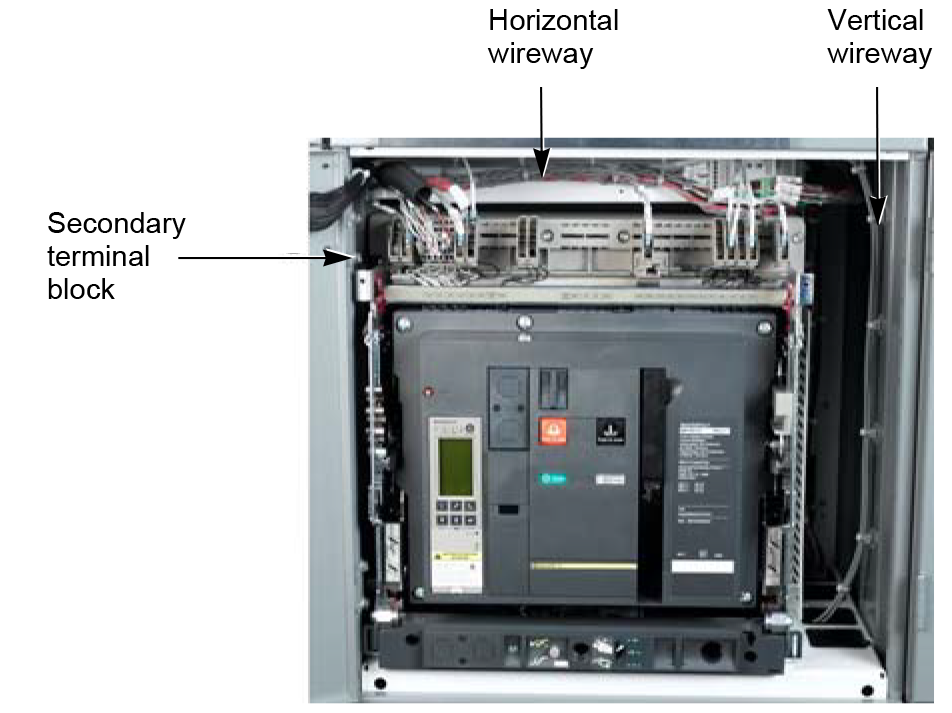
The circuit breaker compartment consists of the circuit breaker cradle, a horizontal secondary terminal block on top of the cradle, and a vertical wireway on the right side of the compartment, allowing for top and bottom customer wiring. The cradle structure is a bolted-in assembly that supports the circuit breaker. Integrated into the cradle are the circuit breaker interference interlocks or cell keys.
Cell keys are steel pins on the left side of the cradle. As the circuit breaker is pushed into the compartment, the keys on the circuit breaker move past corresponding key slots on the cradle. This feature prevents circuit breakers with greater continuous current ratings from being placed in circuit breaker compartments with lesser continuous current ratings. This feature also prevents circuit breakers with lesser short circuit current ratings from being placed in circuit breaker compartments with greater short circuit current ratings.
The racking handle storage space, racking handle insertion opening, and “Stop Release” button are on the bottom of the cradle. Circuit breaker racking is achieved with the circuit breaker compartment door closed.
When required for metering, optional current transformers are positioned around the stationary main contacts or in the bus compartment behind the cell.
 Circuit Breaker Compartment |
Circuit Breaker Compartment with Optional Current Transformers Located Inside the Cell |
MasterPacT Circuit Breaker Ratings
This section contains basic MasterPacT circuit breaker interrupting, sensor, operating time, control power requirements, and switch ampere ratings. In addition, an overview of Key Interlock Operation is described. Most MasterPacT accessories, trip units, and trip unit options are available in Rear Accessible, Front Accessible and Arc Resistant switchgear.
All MasterPacT circuit breakers are 100% rated and are assembled and tested in an ISO 9001 facility to applicable standards including:
| ANSI C37.13 | Low voltage ac power circuit breakers used in equipment |
| ANSI C37.16 | Preferred rating, related requirement and application recommendations for low voltage power circuit breakers and ac power circuit breakers |
| ANSI C37.17 | Trip devices for ac and general-purpose dc low voltage power circuit breakers |
| ANSI C37.50 | Testing of low voltage ac circuit breakers |
| NEMA SG-3 | Low voltage circuit breakers |
| UL 1066 | Low voltage circuit breakers |
Power-Zone 4 switchgear with MasterPacT circuit breakers has the highest interrupting and short-time (withstand) ratings for low voltage switchgear in the smallest physical size. The small switchgear footprint and the elimination of limiters reduces cost. The circuit breaker’s improved coordination with downstream devices increases system uptime.
Power-Zone 4 switchgear using MasterPacT MTZ1/NT circuit breakers allows the use of up to eight (8) 800 A frame circuit breakers in a single, 30-inch wide section. This lets the user maintain a high concentration of power protection devices in a small physical size. MasterPacT MTZ1/NT circuit breakers are not available in Arc Resistant Switchgear.
MasterPacT MTZ2/3, NW circuit breakers are available in various levels of interrupting ratings (AIR) as listed in Ratings for ANSI C37 Certified MasterPacT MTZ2/3 or NW Circuit Breakers below.
Ratings for ANSI C37 Certified MasterPacT MTZ2/3 or NW Circuit Breakers
| Frame Rating | 800/1600 A | 2000 A | 3200 A | 4000/5000 A | |||||||||||||||
|---|---|---|---|---|---|---|---|---|---|---|---|---|---|---|---|---|---|---|---|
| Interrupting Rating Code | N1 | H1 | H2 | H3 | L1*, * | L1F* | H1 | H2 | H3 | L1*, * | L1F* | H1 | H2 | H3 | L1*, * | H2 | H3 | L1 *, * | |
| Interrupting Current (k AIR) | 254 Vac 50/60 Hz | 42 | 65 | 85 | 100 | 200 | 200 | 65 | 85 | 100 | 200 | 200 | 65 | 85 | 100 | 200 | 85 | 100 | 200 |
| 508 Vac 50/60 Hz | 42 | 65 | 85 | 100 | 200 | 200 | 65 | 85 | 100 | 200 | 200 | 65 | 85 | 100 | 200 | 85 | 100 | 200 | |
| 635 Vac 50/60 Hz | 42 | 65 | 85 | 85 | 130 | 130 | 65 | 85 | 85 | 130 | 130 | 65 | 85 | 85 | 130 | 85 | 85 | 130 | |
| Short-Time Withstand Current (kA) | Vac 50/60 Hz, 0.5 s | 42 | 65 | 85 | 85 | 30 | 22 | 65 | 85 | 85 | 30 | 22 | 65 | 85 | 85 | 100 | 85 | 85 | 100 |
| Built In Instantaneous Override (Peak kA ±10%) | —* | —* | —* | 190 | 80* | 55 | — | — | 190 | 80 | 55 | — | — | 190 | 270 | — | — | 270 | |
| Close and Latch Ratings (Peak kA) | Vac 50/60 Hz | 90 | 150 | 90 | 90 | 55 | 50 | 150 | 90 | 90 | 55 | 50 | 150 | 90 | 90 | 90 | 170 | 170 | 90 |
| Tested to show arc flash hazard risk category as referenced by NFPA70E | — | — | — | — | — | Yes | — | — | — | — | Yes | — | — | — | — | — | — | — | |
| Breaking Time | 25 to 30 ms (with no intentional delay) 9 ms for L1 and L1F | ||||||||||||||||||
| Closing Time | 70 ms | ||||||||||||||||||
| Sensor Rating | 100–250 A / 400–800 A for NW / 400–800 A for MTZ2 | 1000–2000 A | 1600–4000 A | 2000–4000 A | |||||||||||||||
| 800–1600 A | 2500–5000 A | ||||||||||||||||||
| Endurance Rating (C/O Cycles) (with no maintenance) | Mechanical | 12,500 | 10,000 | 10,000 | 5000 | 5000 | |||||||||||||
| Electrical | 2800 | 1000 | 1000 | 1000 | 1000 | ||||||||||||||
Ratings for ANSI C37 Certified MasterPacT MTZ1 or NT Circuit Breakers
| Frame Rating | 800 A | |
|---|---|---|
| Interrupting Rating Code | N1 | |
| Interrupting Current (kAIR) | 254 Vac 60 Hz | 42 |
| 508 Vac 60 Hz | 42 | |
| 635 Vac 60 Hz | NA | |
| Short-Time Withstand Current (kA) | ac 60 Hz, 0.5 s | 42 |
| Built-In Instantaneous Override (Peak kA ±10%) | — | |
| Close and Latch Ratings (Peak kA) | ac 60 Hz | 90 |
| Tested to show arc flash hazard risk category as referenced by NFPA70E | — | |
| Breaking Time | 25 to 30 ms (with no intentional time delay) |
|
| Closing Time | < 50 ms | |
| Sensor Rating | 100 to 250 A / 400 to 800 A | |
| Endurance Rating (C/O Cycles) (with no maintenance) | Mechanical | 12,500 |
| Electrical | 2800 | |
Correction Factors
Temperature Correction Factors per ANSI C37.20.1 par. 8.4
| Maximum Ambient Temperature | |||||||||||
|---|---|---|---|---|---|---|---|---|---|---|---|
| °F | 140 | 122 | 104 | 86 | 77 | 68 | 50 | 32 | 14 | –4 | –22 |
| °C | 60 | 50 | 40 | 30 | 25 | 20 | 10 | 0 | –10 | –20 | –30 |
| Current | 0.83 | 0.92 | 1 | 1.07 | 1.11 | 1.14 | 1.21 | 1.27 | 1.33 | 1.39 | 1.44 |
Altitude Correction Factors per ANSI C37.20.1 par. 8.1.3
| < 6600 ft. (2000 m) | 8500 ft (2600 m) | 13,000 ft. (3900 m) | |
|---|---|---|---|
| Voltage | 1 | 0.95 | 0.8 |
| Current | 1 | 0.99 | 0.96 |
MasterPacT MTZ2/3 Circuit Breaker Approximate Operating Time Ratings
|
Action |
Time |
|---|---|
|
Spring
charging motor (MCH) |
|
|
Shunt trip (MX) |
55 milliseconds ± 10 |
|
Shunt close (XF) |
70–80 milliseconds ± 10 |
Control Power-MTZ2/3 Circuit Breakers and PZ-4 Switchgear Equipment
| Action | Power Consumption | |
|---|---|---|
| Spring Charging Motor Current (electrically operated circuit breakers) | 180 VA | |
| Closing coil (XF) | 4.5 VA | |
| Shunt trip coil (MX) | 4.5 VA | |
| Undervoltage with delay unit (MN) | 4.5 VA | |
| Status indicating lights (each) | 2 VA | |
| Power Quality Meter (PM8000/ION9000) | 40 VA/80 VA | |
| Strip heater (each) | Bus Compartment | 125 VA @ 120 Vac |
| Cable Compartment | 125 VA @ 120 Vac | |
| Breaker Compartment | 50 VA @ 120 Vac | |
Approximate Ampere Ratings for MasterPacT MTZ2/3 Circuit Breaker Switches*
| Action | Ampere (240 V) |
|---|---|
| Auxiliary switch (OF)* | 10 A |
| Overcurrent trip switch (SDE) | 5 A |
| Combined (connect/close) switch (EF) | 6 A |
| Cradle cell switch | 8 A |
Circuit Breaker Types
Family of MasterPacT MTZ Circuit Breakers (800–6000 A)
Current Ratings*
| ANSI CB Model Number | Frame Amperes | Sensor Rating | PZ-4 Trip Setting Range | Device Application |
|---|---|---|---|---|
| MTZ2-08N1 | 800 A | 400-800 A | 175-800 A | Feeder |
| MTZ2-08H1 | ||||
| MTZ2-08H2 | ||||
| MTZ2-08H3 | ||||
| MTZ2-08L1* | ||||
| MTZ2-08L1F* | ||||
| MTZ2-16N1 | 1600 A | 800-1600 A | 350-1600 A | Mains/Ties & Feeders |
| MTZ2-16H1 | ||||
| MTZ2-16H2 | ||||
| MTZ2-16H3 | ||||
| MTZ2-16L1* | ||||
| MTZ2-16L1F* | ||||
| MTZ2-20H1 | 2000 A | 1000-2000 A | 400-1600 A | Mains/Ties & Feeders |
| MTZ2-20H2 | ||||
| MTZ2-20H3 | ||||
| MTZ2-20L1* | ||||
| MTZ2-20L1F* | ||||
| MTZ2-32H1 | 3200 A | 1600-3200 A | 700-3200 A | Mains/Ties & Feeders |
| MTZ2-32H2 | ||||
| MTZ2-32H3 | ||||
| MTZ2-32L1* | ||||
| MTZ3-40H2 | 4000 A | 2000-4000 A | 800-4000 A | Mains/Ties & Feeders |
| MTZ3-40H3 | ||||
| MTZ3-40L1* | ||||
| MTZ3-50H2 | 5000 A | 2500-5000 A | 1000-5000 A | Mains/Ties |
| MTZ3-50H3 | ||||
| MTZ3-50L1* | ||||
| MTZ1-08N1 | 800 A | 400-800 A | 175-800 A | Feeders |
 MTZ1 |
 MTZ2 |
 MTZ3 |
Interrupting and Short-Time (Withstand) Capability
Power-Zone 4 switchgear with MasterPacT circuit breakers has the highest interrupting (200,000 A at 480 V without using fuses) and highest short-time (withstand) ratings for low voltage switchgear, in the smallest physical size. The small switchgear footprint and the elimination of limiters reduces cost. The MasterPacT circuit breakers’ wide range of coordination with downstream devices increases system uptime.
MasterPacT circuit breakers are available in various levels of interrupting ratings (AIR).
See Ratings for ANSI C37 Certified MasterPacT Circuit Breakers.
Circuit Breaker Parts
The MasterPacT circuit breaker has fewer parts than conventional circuit beakers while performing the same functions.
Typical MasterPacT Circuit Breaker (Front and Side View of NW shown; MTZ is similar)

The main disconnecting contacts on the rear of the circuit breaker are spring loaded and self-aligning. These contacts are designed so the pressure at the point of contact, on the stationary connectors, becomes greater under short-circuit conditions.

Circuit Breaker Operation
Power-Zone 4 switchgear with MasterPacT circuit breakers has through-the-door circuit breaker racking. The connect, test, and disconnect positions can be made with the circuit breaker compartment door closed.
Circuit Breaker Positions
| Through-the-Door Circuit Breaker Position (side view) |
Primary Connectors | Secondary (Control) Connectors | Circuit Breaker Functionality | Circuit Breaker Door Position | |
|---|---|---|---|---|---|
| Connect |
Engaged | Engaged |
|
Closed | |
| Test |
Disengaged | Engaged |
|
Closed | |
| Disconnect |
Disengaged | Disengaged |
|
Closed | |
| Remove |
Disengaged | Disengaged |
|
Open Circuit breaker is fully extended on rails. |
|
Two-Step Stored Energy Mechanism
Charging the Closing Springs
|
MasterPacT circuit breakers are stored energy devices with a two-step operating mechanism. Electrically operated circuit breakers have a motor to charge the stored energy mechanism, electric close feature, and electric open feature. On manually operated circuit breakers, the closing springs are charged by hand. For electrically operated circuit breakers, the springs are charged by an internal electric motor, but can also be manually charged if no control power is available. Status indicators on the front of the circuit breaker indicate when the closing springs are charged or discharged. |
Circuit Breaker Inspection
When a MasterPacT circuit breaker is withdrawn on its rails, the circuit breaker is accessible for visual inspection. It is easy to remove the arc chutes and visually inspect the contacts and wear indicator. The operations counter can also indicate when inspections and possible maintenance should be done. Health indication for the breaker is also available via front HMI display, mobile device or remote network monitoring. See MicroLogic X/Xi for more information.
MasterPacT Circuit Breaker
 MasterPacT Circuit Breaker on Its Rails |
 MasterPacT Circuit Breaker Front Plate Removed* |
Removable, replaceable, and upgradeable circuit breaker parts include:
-
Arc chutes
-
Main disconnecting contacts or clusters
-
Internal movable contacts
-
Spring charging motor
-
Trip unit
Optional 4-Pole Breaker
4-pole MasterPacT Drawout Circuit Breaker is an optional feature for the following:
-
1600–4000 A Feeders
-
1600–5000 A Mains/Ties
In some electrical systems the user may choose to switch the neutral on and off along with the 3-phases of power to isolate the neutral in multi-source systems. In a 3-pole breaker solution the source neutrals landed at the gear may be connected to multiple sources at the same time which some users wish to avoid by switching the neutral via 4-pole circuit breaker.

The 4-Pole Breaker in LV Drawout equipment opens and closes the phase bus connections as well as the neutral bus connection.
4-pole breakers are available for 1600–5000 A Mains/Ties and 1600–4000 A Feeders (NW, MTZ2 and MTZ3) up to 100 kAIC @ 480 V and 85 kA @ 600 V. Front Accessible and Arc Resistant construction is not available.
-
1600–2000 A = 30” wide section (up to 4 breakers per section)
-
3200 A = 30” wide section (single 3200 A breaker per section)
-
4000–5000 A = 48” wide section (single breaker per section only)
Circuit Breaker and Equipment Accessories
A number of MasterPacT circuit breaker accessories are available with Power-Zone 4 switchgear. A few of the most common accessories are listed below.
 Circuit Breaker Compartment |
Shutters Optional shutters in the cradle automatically block access to the main disconnects when the circuit breaker is in the disconnect, test, or remove position. An optional padlock attachment to lock shutters closed is also available. Key Interlocks, Key Locks, and Padlocks Optional key interlocking can be provided with MasterPacT circuit breakers. Key interlocking capability is available for circuit breaker operation and the cradle. Key interlock operation is outlined in the Power-Zone 4 switchgear order assembly drawings. To facilitate installation procedures, a key is supplied with each lock. After installation, only the necessary keys called out on the key interlock diagrams should be present on the switchgear. |
MasterPacT MTZ2 Circuit Breaker |
Cell Keying Cell keying, a standard feature on Power-Zone 4 switchgear, is provided to avoid insertion of circuit breakers with similar dimensions, but insufficient interrupting ratings, or incorrect frame sizes into an inappropriate circuit breaker compartment. Auxiliary Switches A family of auxiliary switches that include:
|
|
Field-installable and Upgradeable Options A family of field-installable coils, buttons, motors, connectors, and trip units that include, but are not limited to:
|
|
|
Ready-to-close contact (PF): The ready-to-close position switch indicates that the following conditions are met and the circuit breaker can be closed:
|
|
Diagnostic and communicating Shunt Trip (MX), Shunt Close (XF), Undervoltage Trip (MN,diagnostics only) These type of coils bring added functionality with diagnostic and communication capabilities and are only available on MasterPacT MTZ breakers:
|
|
Digital Modules
|
Customize MicroLogic X control unit anytime—Digital modules make it easy to upgrade and tailor your system.
|
|||||||
 |
|||||||
|
Optional digital modules to customize MicroLogic 24/7
|
|||||||
|
NOTE: Refer to the MasterPacT MTZ
Circuit Breakers and Switches catalog (0614CT1701) or MasterPacT
NT and NW Universal Power Circuit Breakers catalog (0613CT0001)
for additional information.
|
|||||||


Key Interlock Operation
As shown in the example below, a main-tie-main manual key interlock scheme is designed to keep all three circuit breakers from being closed simultaneously. Only two of the three circuit breakers can be closed simultaneously.
Main-Tie-Main Key Interlocking
Main 1 and main 2 circuit breakers are closed with their keys placed in the lock cylinders. The tie circuit breaker is locked open; a key is required to unlock it and put the circuit breaker into service.
The main 1 circuit breaker is opened and taken out of service. It is locked open, permitting key A1 to be removed to operate the lock associated with the tie circuit breaker. Then the main 1 circuit breaker cannot be put into service and closed until either the tie circuit breaker, or the main 2 circuit breaker, is opened and locked out of service. This would free one key for use in unlocking the main 1 circuit breaker.