
Technical Overview
This section contains technical data pertaining to Power-Zone 4 standard switchgear, Power-Zone 4 Arc Resistant switchgear, MasterPacT circuit breakers, and MicroLogic trip units. Power-Zone 4 switchgear is industrial-duty equipment built to ANSI standards and uses 100% rated MasterPacT circuit breakers. Switchgear ratings are listed below.
Power-Zone 4 Switchgear Ratings
Equipment Standards
All Power-Zone 4 switchgear are 100% rated and are assembled and tested in an ISO 9001 facility to applicable standards including:
|
Standard |
Description |
|---|---|
|
ANSI C37.20.1 |
Metal-enclosed low voltage circuit breaker switchgear |
|
ANSI C.37.51 |
Testing of metal-enclosed low voltage ac circuit breaker switchgear |
|
ANSI C.37.20.7 |
Guide for Testing Switchgear Rated Up to 52 kV for Internal Arcing Faults |
|
CSA C22.2 No. 31 |
Switchgear assemblies |
|
UBC and CBC |
Zone 4 seismic applications |
|
UL 1558 |
Switchgear assemblies |
Special Applications
This section contains information regarding low voltage systems in seismic and high altitude applications.
Available options for Seismic Applications
Power-Zone 4 switchgear has been tested for applications according to the following codes and regulations:
-
IBC (International Building Code)
-
ASCE 7–10
-
NBCC (National Building Code of Canada)
-
CBC (California Building Code)
-
OSHPD (Office of Statewide Health Planning and Development)
Equipment must be anchored properly to fully comply with zone 4 installations. Additional information can be found in Bulletin No. 80298-002-05, Power-Zone 4 Low Voltage, Metal-Enclosed, Drawout Switchgear with MasterPacT Low Voltage Power Circuit Breakers. Structures are slightly modified with an additional bracket on the base of the structure which are provided for the purpose of seismic anchoring.
High Altitude Applications
When Power-Zone 4 switchgear with MasterPacT circuit breakers is installed at a location greater than 6600 feet above sea level, the equipment ratings must be de-rated (see Altitude Correction Factors per ANSI C37.20.1 par. 8.1.3).
Distribution Systems
This section contains a brief overview of Wye and Delta distribution systems.
Wye Solidly Grounded Systems
A Wye system is the most common type of three-phase distribution system for low voltage switchgear. Wye systems are either three- or four-wire distribution systems that are grounded, either in the equipment (see Four-Wire Wye Distribution (i.e. with Neutral Bus)—Solidly Grounded System - 3 phase, 4 wire), or at the transformer source (see Three-Wire Wye Distribution (i.e. without Neutral bus)—Solidly Grounded System - 3 phase, 3 wire).
Four-Wire Wye Distribution (i.e. with Neutral Bus)—Solidly Grounded System - 3 phase, 4 wire
Three-Wire Wye Distribution (i.e. without Neutral bus)—Solidly Grounded System - 3 phase, 3 wire
When the system is grounded in the equipment and the neutral phase is carried through the equipment, the system is described as a four-wire solidly grounded system with neutral connections available to supply single phase-to-neutral loads, such as lighting loads. Neutral bus is available for distributing the neutral conductor to the loads and can be rated at 50%, 100%, 150% or 200% of the phase bus ampacity depending on bus size.
When the system is grounded at the transformer source and no neutral phase is carried through the equipment, the system is described as a three-wire solidly grounded system (3W Equipment, Neutral Terminated at Source). No neutral connections are available; all loads must be three-phase (or single “phase-to-phase”) loads.
In some cases, the neutral is delivered to the service entrance where it is bonded to ground similar to the four-wire solidly grounded system but the neutral bus is not provided for neutral loads (3W Equipment, Neutral in Incoming Section only).
Delta Grounded and Ungrounded Systems
Delta three-wire systems are rarely used in low voltage distribution systems. Delta three-wire distribution systems can be grounded or ungrounded services. Generally, Delta systems are ungrounded. In some cases, they are grounded on the “corner” of the delta or some other point. Ungrounded Delta systems do not have a reference point or ground. Corner or Grounded B Phase Delta distribution systems do provide a reference point but require one phase to be connected to the ground.
Low voltage drawout switchgear with MasterPacT circuit breakers is designed and built to ANSI C37.20.1 and is tested for single phase-to-phase faults. They can be applied on “corner” grounded Delta distribution systems. Power-Zone 4 switchgear with MasterPacT circuit breakers is suited for corner grounded or ungrounded systems.
Three-Wire Delta Distribution—Ungrounded - 3 phase, 3 wire
Although ungrounded systems have been used for many years, they are not recommended in newly designed low voltage distribution systems. Ungrounded power systems may be unstable. High Resistance Ground Option are recommended for use in newly designed low voltage distribution systems.
Ground Fault Protection for Wye Systems
The need for ground fault protection in three-phase solidly grounded Wye systems is due to the possibility of low magnitude ground fault currents. Phase-to-phase faults are of a magnitude that overcurrent protection devices (trip units) can operate rapidly and positively to signal the circuit breaker to open. Ground faults can be of a much lower magnitude and require specialized elements in the trip unit for detection.
Power-Zone 4 switchgear with MasterPacT circuit breakers equipped with MicroLogic trip units has the capability of providing ground fault sensing (alarm with no tripping) and ground fault protection (tripping) on three-phase, three-wire and three-phase, four-wire solidly-grounded systems. MasterPacT circuit breakers can be used for overcurrent protection on ungrounded or resistance grounded systems, but are not suitable for ground fault protection on these systems.
Ground faults are an inadvertent flow of current between the normal current-carrying conductors and ground. These ground faults usually start at a low level and, if left undetected, escalate causing significant heat and mechanical damage to the electrical system. Ground faults can escalate to a phase-to-phase fault causing major system damage. The ground fault system in the MasterPacT circuit breakers monitors the flow of current in the system and detects ground fault currents. The circuit breaker will trip to protect the circuit, or send an alarm through the appropriate interface equipment, depending on the option installed.
MasterPacT Circuit Breaker Ground Fault System Sensing Capabilities

The National Electrical Code (NEC) requires ground fault protection on solidly grounded Wye electrical services of more than 150 V to ground, but not exceeding 635 V phase-to-phase for each service disconnect rated 1000 A or more. This includes service entrance, feeders and building disconnects. The NEC also requires ground fault alarm (no tripping) on emergency systems and allows ground fault alarm on continuous processes, fire pumps, and other circuits that would be more hazardous if stopped without an orderly shutdown.
Ground Fault Protection with Tripping
Ground fault protection is available as an option on MasterPacT circuit breakers with MicroLogic 6.0X, 6.0Xi, 6.0A, 6.0P or 6.0H trip units. MasterPacT circuit breakers offer three different ground fault sensing options: residual, ground-source return and modified differential. The sensing options make it possible to match the number and location of current sensors to the application. The pickup and delay settings for ground fault are adjustable locally with the dial settings or through the key pad. The pickup and delay settings for ground fault are also adjustable remotely over a computer network on MicroLogic 6.0 and higher trip units. A neutral current sensor (NCT) must be installed in the neutral if ground fault trip is used on a three-phase, four-wire system.
Ground Fault Protection without Tripping
All MasterPacT circuit breakers with MicroLogic 3.0X/Xi, 5.0X/Xi or 6.0X/Xi with optional Ground Fault Alarm Digital Module, 5.0P or 5.0H trip units have the ability to sense and report a ground fault alarm through the optional programmable contact module (M2C or I/O Module) or communication network. A neutral current sensor (NCT) must be installed in the neutral if ground fault alarm is used on a three-phase, four-wire system.
The pickup and delay settings for the ground fault alarm are adjustable locally through the key pad on the trip unit or remotely over a computer network.
Residual Ground Fault Sensing
Residual ground fault sensing systems use one current sensor for each current-carrying conductor. The trip unit vectorially sums the secondary outputs from each sensor to determine if there is a ground fault and the magnitude of the ground fault. The following diagram shows the current sensors for a three-phase, four-wire system. There is a current sensor on each phase and the neutral.
Typical Residual Ground Fault Sensing System with Phase Conductors
The sensors for the phase conductors A, B and C are inside the circuit breaker. The neutral current transformer is installed in the neutral circuit.
Ground Source Return
Ground source return ground fault sensing systems use one current sensor on the ground conductor. The current sensor measures the ground current flow. The following diagram shows the current sensor for a three-phase, four-wire system. Ground source return can also be used on three-phase, three-wire systems.
Typical Ground Source Return Sensing System with Ground Fault Interface Module and Current Sensor
Ground-source return sensing systems require the use of the optional ground fault interface module and a sensor installed in the ground circuit.
The current sensor and ground fault interface module must be wired per the installation and wiring instructions included with the ground fault interface module.
Modified Differential Ground Fault System
A modified differential ground fault system (MDGF) is used for multiple sourced systems. Normal residual and ground-source return systems will not correctly sum all of the circulating currents caused by the multiple neutral paths and multiple grounds. The following diagram shows a typical main-tie-main system. Each source transformer is grounded, and the service entrance neutral is bonded to ground. Multiple neutral paths allow neutral current to circulate and return to the supplying transformer by several different paths. The ground fault system must be capable of correctly summing these circulating currents.
Typical Modified Differential Ground Fault System with Ground Fault Interface Modules
The modified differential ground fault sensing system requires the use of ground fault interface modules and current sensors installed in all normal current-carrying conductors.
The current sensors and ground fault interface modules must be wired in parallel and the polarity of the current sensors must be maintained per the installation and wiring instructions included with the ground fault interface module.
High Resistance Ground Option
When continuity of service for a distribution system is a high priority, high-resistance grounding adds the features of a grounded system on an ungrounded system, while minimizing the risk of service interruptions resulting from ground faults. High resistance grounding simultaneously provides a system reference point (or ground) to overcome the negative effects of low level ground faults and limits the magnitude of current that can flow during a ground fault. A resistance value is selected to limit the overvoltage during arcing faults. Industry practice has established that the resistance value should be selected relative to the system capacitive charging current.
High resistance grounding equipment provides a high resistance grounding circuit for ungrounded power systems. Depending upon the options selected, high resistance grounding equipment offers the following functions:
-
Provides system stability and prevents overvoltages by damping high frequency system oscillations due to ground faults and other system disturbances.
-
Provides a way to detect and warn of the first ground fault that occurs within the system.
-
Provides a means of monitoring the condition of the system voltage in relation to ground potential by means of voltage measurements.
-
In the event of a line-to-ground fault event, provides a way to pulse the ground fault current so the path of ground fault current can be traced by a portable detector.
-
Enables the system to continue to operate with a single line-to-ground fault present.
These functions are accomplished with system neutral grounding adjusted so that ground fault currents are only slightly higher than the natural capacitive charging currents of the ungrounded systems. By selecting the appropriate options, high resistance grounding equipment is available for Wye or Delta ungrounded configured systems rated for 480 and 600 volts nominal. See Diagrams of Wye and Delta Systems.
Diagrams of Wye and Delta Systems
High Resistance Grounding is only available for the following System Voltages:
-
480V 3Ph 3W 60 Hz.
-
600V 3Ph 3W 60 Hz.
-
480Y/277V 3Ph 4W 60 Hz.
-
600Y/347V 3Ph 4W 60 Hz.
Resistor Unit
The resistor unit consists of a group of industrial resistors arranged to provide the proper resistance and capacity to dissipate heat under all operating conditions. The resistor unit may be mounted in an internal compartment in the low voltage equipment. When mounted in the low voltage equipment, the compartment is adequately ventilated to dissipate the heat developed during ground fault conditions. If the desired compartment cannot be sufficiently ventilated, or if one is not available, the equipment resistor unit is mounted on top of the equipment or in some remote location. An example of a ventilated resistor enclosure is shown below in Typical Resistor Assembly
Typical Resistor Assembly

Door Components
Door Component Locations below illustrates the door-mounted components of a typical high resistance ground unit.
Door Component Locations
| 1 | Alarm horn | 7 | Reset/Manual/Auto switch | |
| 2 | Ammeter | 8 | Normal/Pulse switch | |
| 3 | Red light: Ground Fault | 9 | Test button | |
| 4 | Green light: Normal | 10 | Operation nameplate | |
| 5 | Amber light: Pulse On | 11 | Rating nameplate | |
| 6 | Silence button | 12 | Voltmeter |
Automatic Transfer Option
Automatic transfer systems minimize power interruption by transferring the load from the normal source to an alternate source when the normal source is temporarily unavailable. The system uses multiple connections to power sources, usually utility sources, and a programmable logic controller (PLC) to achieve this transfer. These systems also feature redundant supplies of control power. Examples of automatic transfer systems with main-main or generator circuit breakers and main-tie-main or generator circuit breakers are shown in Main-Main (or Generator) Circuit Breaker Configuration and Main-Tie-Main (or Generator) Circuit Breaker Configuration. The system also includes a door mounted Human Machine Interface for password protected control and monitoring of the system via one line based graphics.
HMI Touchscreen Shown on Switchboard/Switchgear door

One-Line Screen view for HMI with Automatic Transfer System
Main-Main or Main-Generator Option
Each main circuit breaker connects to a utility source or one main circuit breaker connects to a utility source and the other man circuit breaker connects to a generator source. When the normal source becomes unavailable, the system transfers to the alternate. If the system comes equipped with a preferred source selector option, the system reverts to the preferred source automatically once it is available. Without the selector, automatic retransfer does not occur.
Optional listing to UL 1008 for both closed and open transition transfer schemes is available. When an open transition UL 1008 listed transfer scheme is specified, a mechanical interlocking cable is provided between the two main circuit breakers (main-main or main-generator) to assure that at least one circuit breaker is always open. This way, one circuit breaker is open prior to closing the other main.
Main-Main (or Generator) Circuit Breaker Configuration
The PLC based, breaker-based automatic transfer design from Schneider Electric are designed to meet Underwriters Laboratories (UL) 1008 and to be applied on National Electrical Code® (NEC®) 700, Emergency Systems. They are also applicable to NEC 701, Legally-Required Standby Systems and NEC 702, Optional Standby Systems.
Main-Tie-Main or Main-Tie-Generator Option
Both main circuit breakers, connected to a utility source, are connected together by means of a normally open tie circuit breaker.
Main-Tie-Main (or Generator) Circuit Breaker Configuration
Layout Arrangement for Main-Tie-Main Power-Zone 4 Lineup Automatic Transfer PLC Solution

Full Sequences of Operation for these pre-engineered PLC Automatic transfer Systems can be obtained by contacting Schneider Electric.
Basic Electrically Operated Circuit Breaker Diagrams
This section contains MasterPacT circuit breaker diagrams. Refer to catalog MasterPacT MTZ Circuit Breakers and Switches 0614CT1701 for additional information.
MasterPacT MTZ1 Drawout Devices
The diagram is shown with circuits de-energized, all devices open, connected and charged and relays in normal position.
|
Power* |
Control Unit |
Indication Contacts |
|---|---|---|
|
NOTE: It is possible to add a second MX/MX diag&com or a MN/MN diag
voltage release. The second MX diag&com voltage release can only
be installed after the delivery of the circuit breaker. This is an
after-sales adaptation.
|
||
|
Remote Operation* |
|---|
|
NOTE: Maximum length of the two wires
between A2–A3,/C20C3/C12/C13: 5 m (16 ft.).
For the maximum length of the wiring between the AC/DC power supply and the voltage release terminals A1–A3/C1–C3/C11–C13/D1–D2: see Shunt Close (XF), Shunt Trip (MX), and Undervoltage Release (MN) with Basic Coils. |
Terminal Block Marking
|
Indication Contacts Terminal Bock |
Control Unit Terminal Block |
||||
|
OF4 / OF3 / OF2 / OF1 : Open/closed indication contacts OF |
Com : |
ULP Communication |
|||
|
Cradle Contacts Terminal Block |
UC1 : |
Z1-Z4 Zone Selective Interlocking |
|||
|
CD2 / CD1: |
Disconnected position contacts |
UC2 : |
T1, T2 = Neutral External Sensors |
||
|
CE3 /CE2 / CE1: |
Connected position contacts |
UC3 : |
Voltage Connector (must be connected to the neutral with a 3P circuit breaker) |
||
|
CT1: |
Test position contacts |
||||
|
UC4 : |
External Voltage Connector (PTE option) |
||||
|
Remote Operation Terminal Block |
|||||
|
SDE2: |
Overcurrent Trip Indication Contact |
||||
|
SDE1: |
Overcurrent Trip Indication Contact (supplied as standard) |
||||
|
MN /MN diag: |
Undervoltage Release Standard or Diagnostic |
||||
|
MX/MX diag&com: |
Shunt Trip Standard or Diagnostic & Communicating |
||||
|
2nd MX/MX diag&com: |
Shunt Trip Standard or Diagnostic |
||||
|
XF/XF diag&com: |
Shunt Close Standard or Diagnostic & Communicating |
||||
|
PF: |
Ready-to-Close Contact |
||||
|
MCH: |
Spring Charging Motor |
||||
|
NOTE: When communicating MX diag&com or XF diag&com accessories
are used, the third wire (C3,A3, C13) must be connected even if the
communication module is not installed.
|
|||||
MasterPacT MTZ2/MTZ3 Drawout Devices
The diagram is shown with circuits de-energized, all devices open, connected and charged and relays in normal position.
|
Power * |
Control Unit |
|---|---|
|
Remote Operation* |
|---|
|
Indication Contacts |
Cradle Contacts |
|
Control Unit Terminal Block |
Remote Operation Terminal Block |
|||
|---|---|---|---|---|
|
Com : |
ULP communication |
SDE2: |
Overcurrent
trip indication contact |
|
|
UC1 : |
Z1-Z4 Zone Selective Interlocking |
|||
|
UC2 : |
T1, T2 = Neutral External Sensors |
SDE1: |
Overcurrent Trip Indication Contact (Supplied as Standard) |
|
|
MN /MN diag: |
Undervoltage Release Standard or Diagnostic |
|||
|
UC3 : |
Voltage Connector (must be connected to the neutral with a 3P circuit breaker) |
MX/MX diag&com: |
Shunt Trip Standard or Diagnostic & Communicating |
|
|
UC4 : |
External Voltage Connector (PTE option) |
2nd MX/MX diag&com: |
Shunt Trip Standard or Diagnostic |
|
|
XF/XF diag&com: |
Shunt Close Standard or Diagnostic & Communicating |
|||
|
PF: |
Ready-to-Close Contact |
|||
|
MCH: |
Spring Charging Motor |
|||
|
NOTE: When
communicating MX com or XF com accessories are used, the third wire
(C3,A3, C13) must be connected even if the communication module is
not installed.
|
||||
Terminal Block Marking
Conduit Area Dimensions
60 in. Deep Feeder Sections (36W/30W/22W), Rear Accessible, Top and Bottom Conduit Entrance Dimensions – Not for Construction (consult factory drawings)

72 in. Deep Feeder Sections (36W/30W/22W), Rear Accessible, Top and Bottom Conduit Entrance Dimensions – Not for Construction (consult factory drawings)

80 in. Deep Feeder Sections (36W/30W/22W), Rear Accessible, Top and Bottom Conduit Entrance Dimensions – Not for Construction (consult factory drawings)

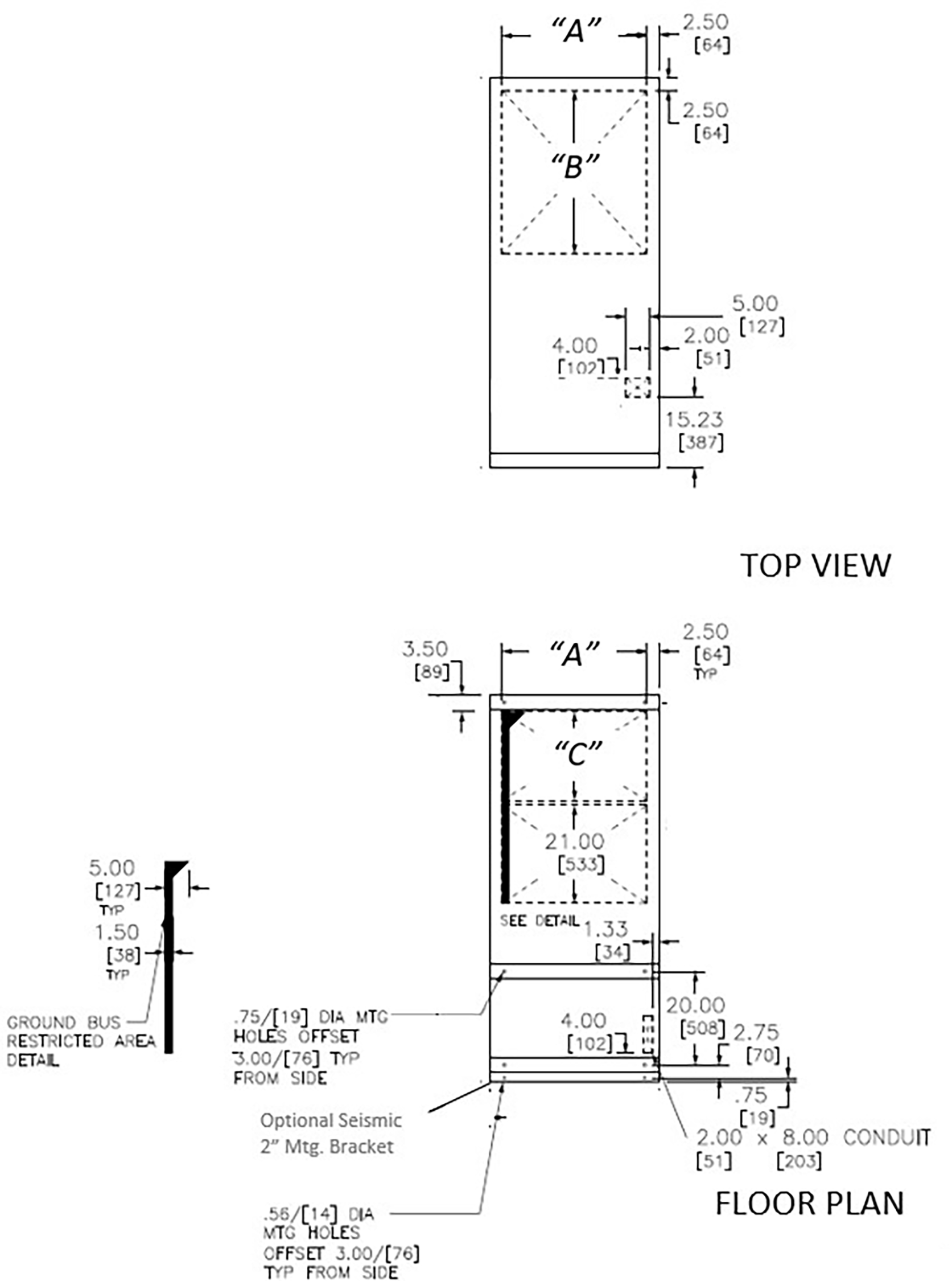
Incoming Main Section with Top Incoming Cable, Rear Accessible, Conduit Entrance Dimensions – Not for Construction (consult factory drawings)

| Dimension | 22 in. W | 36 in. W |
|---|---|---|
| A | 17 in. | 31 in. |
| Dimension | 60 in. D* | 72 in. D | 80 in. D |
|---|---|---|---|
| B | 0 in. | 12 in. | 20 in. |
| C | 14 in. | 26 in. | 34 in. |
Incoming Main Section with Bottom Incoming Cable, Rear Accessible, Conduit Entrance Dimensions – Not for Construction (consult factory drawings)
| Dimension | 22 in. W | 36 in. W |
|---|---|---|
| A | 17 in. | 31 in. |
| Dimension | 60 in. D* | 72 in. D | 80 in. D |
|---|---|---|---|
| B | 15 in. | 27 in. | 35 in. |
| C | 0 in. | 11 in. | 19 in. |
Incoming Main Section, Close-Coupled to Square D Transformer, Rear Accessible, Conduit Entrance Dimensions – Not for Construction (consult factory drawings)

| Dimension | 22 in. W | 36 in. W |
|---|---|---|
| A | 17 in. | 31 in. |
| Dimension | 60 in. D | 72 in. D | 80 in. D |
|---|---|---|---|
| B | 12 in. | 25 in. | 33 in. |
| C | 14 in. | 26 in. | 34 in. |
Main with Feeders OR Feeders Only Section, Top or Bottom Incoming Cable, Front Accessible, Conduit Entrance Dimensions – Not for Construction (consult factory drawings)

| Dimension | 44 in. W | 52 in. W | 58 in. W |
|---|---|---|---|
| A | 18.5 in. | 26.5 in. | 32.5 in. |
| B | 24.5 in. | 32.5 in. | 38.5 in. |
26W Main without Feeders Section, Top or Bottom Incoming Cable, Front Accessible, Conduit Entrance Dimensions – Not for Construction (consult factory drawings)

NEMA 3R Walk-in Low Voltage Switchboard/Switchgear Top Conduit Entrance Dimensions–Not for Construction (consult factory drawings)

-
This dimension corresponds to 72-inch PZ-4/QED-6 equipment.
-
This dimension corresponds to 80-inch PZ-4/QED-6 equipment.
NEMA 3R Walk-in Low Voltage Switchboard/Switchgear Bottom Conduit Entrance Dimensions–Not for Construction (consult factory drawings)

-
This dimension corresponds to 72-inch PZ-4/QED-6 equipment.
-
This dimension corresponds to 80-inch PZ-4/QED-6 equipment.
-
Location of Anchor Bolts (3) at both ends by user; min. 0.5 in. (12.5 mm).
Arc Resistant Construction Notes:
-
Use Rear Accessible NEMA Type 1 figures above for Conduit Entry dimensions but add 6.5" to depth of Top View openings and reduce depth of Floor Plan openings by 6.5" due to ventilation duct.
-
Section depth will grow (+4.00-in./102 mm) where fans (5000 A riser bus) are required (see Fan Mounting Plate).
-
Arc Resistant Construction is not available in NEMA Type 3R Walk-In or Front Accessible Enclosures.
-
30 in. (762 mm) wide structures are not available.
-
Control conduit openings are available on top of section as shown below.
Layout Arrangements and Section Widths
Available Breaker Positions — 3-Pole, Rear Accessible Feeder Sections
It is required to use the Schneider Electric Low Voltage Drawout product selector tool for proper layout. Some arrangements may not be possible due to factors such as conduit space, cable sizing, system bus ampacity, etc. Section Depth (60, 72 or 80 in.) will determine final arrangement based on conduit entry space available. All conduit entry space is calculated based on 500 kcmil copper cables in 3.5 in. conduits. Cables are assumed to have 90°C insulation rating and sized per 75°C tables in NEC Table 310.16. Operating load current of sections cannot exceed main(s) ampacity.
| Cell A | 800– 2000 A* Feeder |
800– 1600 A Feeder |
800– 1600 A Feeder |
800– 1600 A Feeder |
||||
| Cell B | 800– 2000 A* Feeder |
800– 1600 A Feeder |
800– 1600 A Feeder |
3200
A Feeder (100 kAIC Max.) |
||||
| Cell C | 800–2000 A* Feeder | 800–1600 A Feeder | 3200
A Feeder (100 kAIC Max.) |
800–1600 A Feeder | ||||
| Cell D | 800–2000 A* Feeder | 3200
A Feeder (100 kAIC Max.) |
800–1600 A Feeder | 800–1600 A Feeder | ||||
| 22 in. W | 22 in. W | 22 in. W | 22 in. W |
| Cell A | 800–2000
A* Feeder |
800–2000
A* Feeder |
800 MTZ1 Feeder |
800 MTZ1 Feeder |
800–2000 A* Feeder |
||||
| Cell B | 3200 A Feeder (100 kAIC Max.) 4000 A Feeder |
800–2000 A* | 800 MTZ1 Feeder | 800 MTZ1 Feeder | 800–2000
A* Feeder |
||||
| Cell C | 3200 A Feeder (above 100 kAIC) 4000 A Feeder |
800 MTZ1 Feeder | 800 MTZ1 Feeder | 800–2000
A* Feeder |
|||||
| Cell D | 800–2000 A* Feeder | 800 MTZ1 Feeder | 800 MTZ1 Feeder | 800–2000
A* Feeder |
|||||
| 36 in. W | 36 in. W | 30 in. W | 30 in. W | ||||||
Available Breaker Positions — 3-Pole, Rear Accessible Main Sections
It is required to use the Schneider Electric Low Voltage Drawout product selector tool for proper layout. Some arrangements may not be possible due to factors such as conduit space, cable sizing, system bus ampacity, etc. Section Depth (60, 72 or 80 in.) will determine final arrangement based on conduit entry space available. All conduit entry space is calculated based on 500 kcmil copper cables in 3.5 in. conduits. Cables are assumed to have 90°C insulation rating and sized per 75°C tables in NEC Table 310.16. Operating load current of sections cannot exceed main(s) ampacity.
| Cell A | Factory Use Instrument Compartment | 800– 2000 A* Feeder |
Factory Use Instrument Compartment | 800– 2000 A* Feeder |
|||
| Cell B | 1600– 2000 A Top Entry Main (100 kAIC or less) |
1600– 2000 A Top Entry Main (100 kAIC or less) |
3200 A Top Entry Main (100 kAIC or less) |
800– 2000 A*Feeder |
|||
| Cell C | 800– 2000 A* Feeder |
Blank or IC | 800– 2000 A* Feeder |
3200 A Bottom Entry Main (100 kAIC or less) |
|||
| Cell D | 800–2000 A* Feeder | Factory Use Instrument Compartment | 800–2000 A* Feeder | Factory Use Instrument Compartment | |||
| 22 in. W* | 22 in. W* | 22 in. W | 22 in. W |
Available Breaker Positions — 3-Pole, Rear Accessible Tie Sections
It is required to use the Schneider Electric Low Voltage Drawout product selector tool for proper layout. Some arrangements may not be possible due to factors such as conduit space, cable sizing, system bus ampacity, etc. Section Depth (60, 72 or 80 in.) will determine final arrangement based on conduit entry space available. All conduit entry space is calculated based on 500 kcmil copper cables in 3.5 in. conduits. Cables are assumed to have 90°C insulation rating and sized per 75°C tables in NEC Table 310.16. Operating load current of sections cannot exceed main(s) ampacity.
| Cell A | 800–2000 A* Feeder | 800–2000 A* Feeder | |
| Cell B | 1600–3200
A Tie* (100 kAIC or less) |
1600–3200 A Tie* (above 100 kAIC) 4000–5000 A Main |
|
| Cell C | 800–2000 A* Feeder | ||
| Cell D | 800–2000 A* Feeder | 800–2000 A* Feeder | |
| 22 in. W | 36 in. W |
| Cell A | 800–2000 A* Feeder | 800–2000 A* Feeder | 800–2000 A* Feeder | 800–2000 A* Feeder | |
| Cell B | Tie with Transition* 1600–3200 A Tie (100 kAIC or less) |
800–2000 A* Feeder | Tie with Bus Transition Section* 1600–3200
A Tie (above 100 kAIC) 4000–5000 A Main |
800–2000 A* Feeder | |
| Cell C | 800–2000 A* Feeder | 800–2000 A* Feeder | 800–2000 A* Feeder | ||
| Cell D | 800–2000 A* Feeder | 800–2000 A* Feeder | 800–2000 A* Feeder | 800–2000 A* Feeder | |
| 22 in. W | 22 in. W | 36 in. W | 22 in. W |
Available Breaker Positions — 4-Pole, Rear Accessible Sections
It is required to use the Schneider Electric Low Voltage Drawout product selector tool for proper layout. Some arrangements may not be possible due to factors such as conduit space, cable sizing, system bus ampacity, etc. Section Depth (60, 72 or 80 in.) will determine final arrangement based on conduit entry space available. All conduit entry space is calculated based on 500 kcmil copper cables in 3.5 in. conduits. Cables are assumed to have 90°C insulation rating and sized per 75°C tables in NEC Table 310.16. Operating load current of sections cannot exceed main(s) ampacity.
| Cell A | Blank or IC | 1600–2000 A Feeder | Factory Use Instrument Compartment | 1600–2000 A Feeder | Blank or IC | Blank or IC | |||||
| Cell B | 4000–5000 A Main/Tie Or 4000 A Feeder | 1600–2000 A Feeder | Top Entry 3200 A Main |
Bottom Entry 3200 A Main |
3200 A Feeder | 1600–2000 A Feeder | |||||
| Cell C | 1600–2000 A Feeder | 3200 A Feeder | |||||||||
| Cell D | Blank or IC | 1600–2000 A Feeder | 1600–2000 A Feeder | Factory Use Instrument Compartment | 1600–2000 A Feeder | ||||||
| 48 in. W | 30 in. W | 30 in. W | 30 in. W | 30 in. W | 30 in. W |
Available Breaker Positions — Front Accessible Feeder Sections
It is required to use the Schneider Electric Low Voltage Drawout product selector tool for proper layout. Some arrangements may not be possible due to factors such as conduit space, cable sizing, system bus ampacity, etc. Final arrangement will be based on conduit entry space available. All conduit entry space is calculated based on 500 kcmil copper cables in 3.5 in. conduits. Cables are assumed to have 90°C insulation rating and sized per 75°C tables in NEC Table 310.16. Operating load current of sections cannot exceed main(s) ampacity.
Front Accessible Switchgear may require longer and heavier shipping splits than traditional Rear Accessible Switchgear. In some Front Accessible cases 92 in. wide (2235.2 mm) and 8000 lb. (3629 kg) shipping splits will be provided. Customer should review Front Accessible factory supplied approval or record drawings to determine provisions for equipment handling and moving around obstructions at site. For questions on Front Accessible Switchgear, contact your local Schneider Electric Representative.
| 800–2000 A Feeder | Cable Compartment | 800–2000 A Feeder | Cable Compartment |
800–2000 A Feeder | Cable Compartment |
||
| 800–2000 A Feeder | 800–2000 A Feeder | 800–2000 A Feeder | |||||
| 800–2000 A Feeder | 800–2000 A Feeder | 800–2000 A Feeder | |||||
| 800–2000 A Feeder | 800–2000 A Feeder | 800–2000 A Feeder | |||||
| 44 in. W | 52 in. W | 58 in. W | |||||
Available Breaker Positions — Front Accessible Incoming Main without Feeder Sections
| Top Incoming Cable Compartment | Factory Use Instrument Compartment | |
| 1600–3200 A Main Circuit Breaker | ||
| 1600–3200 A Main Circuit Breaker | Bottom Incoming Cable Compartment | |
| Factory Use Instrument Compartment | ||
| 26 in. W | 26 in. W |
Available Breaker Positions — Front Accessible Main with Feeder Sections
It is required to use the Schneider Electric Low Voltage Drawout product selector tool for proper layout. Some arrangements may not be possible due to factors such as conduit space, cable sizing, system bus ampacity, etc. Final arrangement will be based on conduit entry space available. All conduit entry space is calculated based on 500 kcmil copper cables in 3.5 in. conduits. Cables are assumed to have 90°C insulation rating and sized per 75°C tables in NEC Table 310.16. Operating load current of sections cannot exceed main(s) ampacity.
Front Accessible Switchgear may require longer and heavier shipping splits than traditional Rear Accessible Switchgear. In some Front Accessible cases 92 in. wide (2235.2 mm) and 8000 lb. (3629 kg) shipping splits will be provided. Customer should review Front Accessible factory supplied approval or record drawings to determine provisions for equipment handling and moving around obstructions at site. For questions on Front Accessible Switchgear, contact your local Schneider Electric Representative.
| Factory Use Instrument Compartment | Incoming Mains Cable Compartment | Factory Use Instrument Compartment | Incoming Mains Cable Compartment | Factory Use Instrument Compartment | Cable Compartment | ||
| 1600–3200 A Top Main Entry | 1600–3200 A Top Main Entry | 1600–3200 A Top Main Entry | |||||
| Feeders Cable Compartment | Feeders Cable Compartment | Feeders Cable Compartment | |||||
| 800–2000 A Feeder (Bottom Exit Only) |
800–2000
A Feeder (Bottom Exit Only) |
800–2000
A Feeder (Bottom Exit Only) |
|||||
| 800–2000 A
Feeder (Bottom Exit Only) |
800–2000
A Feeder (Bottom Exit Only) |
800–2000
A Feeder (Bottom Exit Only) |
|||||
| 44 in. W | 52 in. W | 58 in. W | |||||
| 800–2000 A Feeder (Top Exit Only) |
Feeders Cable Compartment | 800–2000 A Feeder (Top Exit Only) |
Feeders Cable Compartment | 800–2000 A Feeder (Top Exit Only) |
Feeders Cable Compartment | ||
| 800–2000 A Feeder (Top Exit Only) |
800–2000 A Feeder (Top Exit Only) |
800–2000 A Feeder (Top Exit Only) |
|||||
| 1600–3200
A Bottom Entry Main |
1600–3200 A Bottom Entry Main |
1600–3200 A Bottom Entry Main |
|||||
| Incoming Mains Cable Compartment | Incoming Mains Cable Compartment | Incoming Mains Cable Compartment | |||||
| Factory Use Instrument Compartment | Factory Use Instrument Compartment | Factory Use Instrument Compartment | |||||
| 44 in. W | 52 in. W | 58 in. W | |||||
58 in. W required for 4-Wire neutral or Surge Protective Device options.
Available Breaker Positions — Front Accessible Tie Sections
It is required to use the Schneider Electric Low Voltage Drawout product selector tool for proper layout. Some arrangements may not be possible due to factors such as conduit space, cable sizing, system bus ampacity, etc. Final arrangement will be based on conduit entry space available. All conduit entry space is calculated based on 500 kcmil copper cables in 3.5 in. conduits. Cables are assumed to have 90°C insulation rating and sized per 75°C tables in NEC Table 310.16. Operating load current of sections cannot exceed main(s) ampacity.
Front Accessible Switchgear may require longer and heavier shipping splits than traditional Rear Accessible Switchgear. In some Front Accessible cases 92 in. wide (2235.2 mm) and 8000 lb. (3629 kg) shipping splits will be provided. Customer should review Front Accessible factory supplied approval or record drawings to determine provisions for equipment handling and moving around obstructions at site. For questions on Front Accessible Switchgear, contact your local Schneider Electric Representative.
| Factory Use Instrument Compartment | Factory Use Instrument Compartment | Feeders Cable Compartment | |
| 1600–3200 A Tie | 1600–3200 A Tie | ||
| Blank/Instrument Compartment | 800–2000 A Feeder | ||
| Blank/Instrument Compartment | 800–2000 A Feeder | ||
| 22 in. W Tie without Feeders* | 44 in. or 52 in. W Tie with Feeders option* | ||
| Factory Use Instrument Compartment | 800–2000 A Feeder | Feeders Cable Compartment |
| 1600–3200 A Tie | 800–2000 A Feeder | |
| Blank/Instrument Compartment | 800–2000 A Feeder | |
| Blank/Instrument Compartment | 800–2000 A Feeder | |
| 66, 74, or 80 in. W Tie with Bus Transition* | ||
Front View, NEMA 1, Rear Accessible, Non-Arc Resistant Low Voltage Switchgear
Front View, NEMA 1, Rear Accessible, Arc Resistant Low Voltage Switchgear (with Baffle Option)
Front View, NEMA 1, Rear Accessible, Arc Resistant Low Voltage Switchgear (with Plenum Option)
Front View, NEMA 1, Front Accessible, Low Voltage Switchgear
Front View, NEMA 3R Walk-in Low Voltage Switchboard/Switchgear

Right Side View, NEMA 3R Walk-in Low Voltage Switchboard/Switchgear

System Source Applications and Selection
Single Main

Lineup contains only one(1) incoming main from utility, transformer, or generator. The purpose of the single main is to disconnect all incoming conductors from the source.
-
Source may be connected to the lineup via Cable, Close Coupled to Transformer or Busway.
-
No tie breakers are required in Single Main configuration.
Main can be top or bottom incoming. The Main can be on the left or right side of the lineup. All feeders on left located main can only be located to the right of the main. All feeders on right located main can only be located to the left of the main.
End Fed Main-Tie-Main

Lineup contains two (2) incoming mains from utility or upstream transformer. The purpose of the Main-Tie-Main configuration is to allow the feeders to be supplied power from 2 sources with a tie breaker disconnect between Bus “A” and Bus “B”. The normally open tie isolates the 2 buses both electrically (when open) and physically with barriers. In case one utility main is unavailable the feeders can all be fed from the remaining available source by closing the tie. The opening and closing of the mains/tie for various operating conditions are controlled by automatic source controllers or key interlocking.
-
Sources may be connected to the lineup via Cable, Close Coupled to Transformer or Busway
Mains can be the same incoming direction (both top, both bottom) or be top incoming on one and bottom incoming on the other. End Fed Main-Tie-Main will have the main disconnects physically and electrically located at the left and right ends of the lineup. All feeders will be in between the mains and separated by the tie as shown in the figure above.
When both mains have incoming direction the same the tie breaker must have an additional bus transition section on its right side to properly locate the horizontal cross bus to the top or bottom.

In the case of the 2 mains having different incoming directions the addition of a bus transition is not necessary.
Multiple Tie Breakers are available by contacting the Schneider Electric factory.
End Fed Main-Tie-Generator

Lineup contains one (1) incoming main from utility or upstream transformer AND one (1) incoming main disconnect for backup generator source. The purpose of the Main-Tie-Generator configuration is to allow all feeders in the lineup to be supplied power from Main 1 (normally closed) and the Tie breaker (normally closed). The Generator and its Main 2 (normally open) are available as a backup source in case the Main 1 source is unavailable. The Tie breaker opens during a transfer to the generator. The opening and closing of the mains/tie for various operating conditions are controlled by automatic source controllers or key interlocking.
-
Sources may be connected to the lineup via Cable, Close Coupled to Transformer or Busway (
Mains can be the same incoming direction (both top, both bottom) or be top incoming on one and bottom incoming on the other. End Fed Main-Tie-Generator will have the main disconnects physically and electrically located at the left and right ends of the lineup and cannot be moved. The Generator Main can be selected to be on the right or left end of the lineup. All feeders will be in between the mains and separated by the tie as shown in the figure above.
When both mains have incoming direction the same the tie breaker must have an additional bus transition section on its right side to properly locate the horizontal cross bus to the top or bottom.
In the case of the 2 mains having different incoming directions the addition of a bus transition is not necessary.
End Fed Main-Tie-Generator allows for a maximum two (2) Main Breakers. When more than 2 incoming mains with options are required contact Schneider Electric factory.
Multiple Tie Breakers are available by contacting the Schneider Electric factory.
End Fed Main-Generator

Lineup contains one (1) incoming main from utility or upstream transformer AND one (1) incoming main disconnect for backup generator source. The purpose of the Main-Generator configuration is to allow all feeders in the lineup to be supplied power from Main 1 (normally closed). The Generator and its Main 2 (normally open) are available as a backup source in case the Main 1 source is unavailable or there is a source 1 power failure. The opening and closing of the mains for various operating conditions are controlled by automatic source controllers or key interlocking.
-
Sources may be connected to the lineup via Cable, Close Coupled to Transformer or Busway.
Mains can be the same incoming direction (both top, both bottom) or be top incoming on one and bottom incoming on the other. End Fed Main-Generator will have the main disconnects physically and electrically located at the left and right ends of the lineup and cannot be moved. The Generator Main can be selected to be on the right or left end of the lineup. All feeders will be in between the mains as shown in the figure above.

In the case of the 2 mains having same incoming directions the addition of a bus transition is not necessary.
End Fed Main-Generator allows for a maximum two (2) Main Breakers. When more than 2 incoming mains with options are required contact Schneider Electric factory.
End Fed Main-Main

Lineup contains two (2) incoming mains from utility or upstream transformer. The purpose of the Main-Main configuration is to allow all feeders in the lineup to be supplied power from Main 1 (normally closed). Main 2 (normally open) is available as a backup source in case the Main 1 source is unavailable or there is a source 1 power failure. The opening and closing of the mains for various operating conditions are controlled by automatic source controllers or key interlocking.
-
Sources may be connected to the lineup via Cable, Close Coupled to Transformer or Busway.
Mains can be the same incoming direction (both top, both bottom) or be top incoming on one and bottom incoming on the other. End Fed Main-Main will have the main disconnects physically and electrically located at the left and right ends of the lineup and cannot be moved. All feeders will be in between the mains as shown in the figure above.

In the case of the 2 mains having same incoming directions the addition of a bus transition is not necessary.
If more than 2 incoming mains are required contact Schneider Electric factory.
Center Fed Main-Tie-Main

Similar in features to the End Fed Main-Tie-Main except Center Fed Main-Tie-Main will have the main disconnects physically and electrically located in between all feeders. All feeders will be located to the right or left of the mains and separated by the tie as shown in the figure above. Feeders cannot be placed in between the mains as this would not be a Center Fed topology.
When both mains have incoming direction the same the tie breaker must have an additional bus transition section on its right side to properly locate the horizontal cross bus to the top or bottom. In the case of Center Fed Main-Tie-Main.
In the case of the 2 mains having different incoming directions the addition of a bus transition is not necessary.
Multiple Tie Breakers are available by contacting the Schneider Electric factory.
Center Fed Main-Tie-Generator

Similar in features to the End Fed Main-Tie-Generator except Center Fed Main-Tie-Generator will have the main disconnects physically and electrically located in between all feeders. The Generator Main can be selected to be on the right or left side of the tie in the lineup. All feeders will be located to the right or left of the mains and separated by the tie as shown in the figure above. Feeders cannot be placed in between the mains as this would not be a Center Fed topology.
When both mains have incoming direction the same the tie breaker must have an additional bus transition section on its right side to properly locate the horizontal cross bus to the top or bottom. Feeders cannot be placed in this additional bus transition section in the case of Center Fed Main-Tie-Main.
In the case of the 2 mains having different incoming directions the addition of a bus transition is not necessary.
If more than one Tie Breaker or multiple Generator Breakers are required contact the Schneider Electric factory.
Center Fed Main-Generator

Similar in features to the End Fed Main-Generator except Center Fed Main-Generator will have the main disconnects physically and electrically located in between all feeders. The Generator Main can be selected to be on the right or left side of the utility main. All feeders will be located to the right or left of the mains as shown in the figure above. Feeders cannot be placed in between the mains as this would not be a Center Fed topology.

In the case of the 2 mains having same incoming directions the addition of a bus transition is not necessary.
If more multiple Generator Breakers are required contact the Schneider Electric factory.
Center Fed Main-Main

Similar in features to the End Fed Main-Main except Center Fed Main-Main will have the main disconnects physically and electrically located in between all feeders. All feeders will be located to the right or left of the mains as shown in the figure above. Feeders cannot be placed in between the mains as this would not be a Center Fed topology.

In the case of the 2 mains having same incoming directions the addition of a bus transition is not necessary.
If more than 2 incoming mains are required contact Schneider Electric factory.
Parallel Generators

End Fed Main-Tie-Tie-Main

Lineup contains two (2) incoming mains from utility or upstream transformer AND two (2) tie breakers. The purpose of the Main-Tie-Tie-Main configuration is to allow the feeders to be supplied power from 2 sources with two (2) tie breaker disconnects between Bus “A” and Bus “B”. In the normal state one tie is closed and one is open. The two (2) ties configuration provides additional maintenance advantages vs. one (1) tie configuration. For example, maintenance can be performed on one of the ties creating a state where it is fully de-energized on both sides by opening the other tie (assuming the ties are in separate sections and the main feeding the corresponding tie is open). Additionally, for load flexibility feeders can be added between the two (2) tie breakers to allow either bus to feed loads between the ties in case one source is unavailable. Both ties can be opened to de-energize the loads between them.
Much like the single tie configuration, in case one utility main is unavailable the feeders can all be fed from the remaining available source by closing both ties. The opening and closing of the mains/ties for various operating conditions are controlled by automatic source controllers or key interlocking.
Sources may be connected to the lineup via Cable, Close Coupled to Transformer or Busway.
Center Fed Main-Tie-Tie-Main

End Fed Main-Tie-Tie-Generator

Center Fed Main-Tie-Tie-Generator
