
Connect the Signal Cables from Switchgear and Third-Party Auxiliary Products
Overview of Signal Connection Terminals in the UPS

NOTE: Route the signal cables separately from the power cables
and route the Class 2/SELV cables separately
from the non-Class 2/non-SELV cables.
- Install the temperature sensor provided with the UPS in
the battery solution. In battery cabinets, install the temperature
sensor in the top corner of the battery cabinet.
 WARNINGHazard of firePosition the temperature sensor as described to ensure correct temperature measurements.Failure to follow these instructions can result in death, serious injury, or equipment damage.
 - Route the battery temperature sensor cables from the battery
solution to the UPS and connect as shown.NOTE: Two temperature sensors are provided with the UPS.NOTE: The battery temperature sensor cables are considered Class 2/SELV. Class 2/SELV circuits must be isolated from the primary circuitry.

- Connect signal cables from the disconnect device indicator
lights in your switchgear to terminal J6618 in the top of the UPS.
If an external supply is used, remove jumper from J6618 pin 8 and
9.NOTE: The disconnect device indicator light circuit is considered Class 2/SELV. Class 2/SELV circuits must be isolated from the primary circuitry. Do not connect any circuit to the disconnect device indicator light terminals unless it can be confirmed that the circuit is Class 2/SELV.

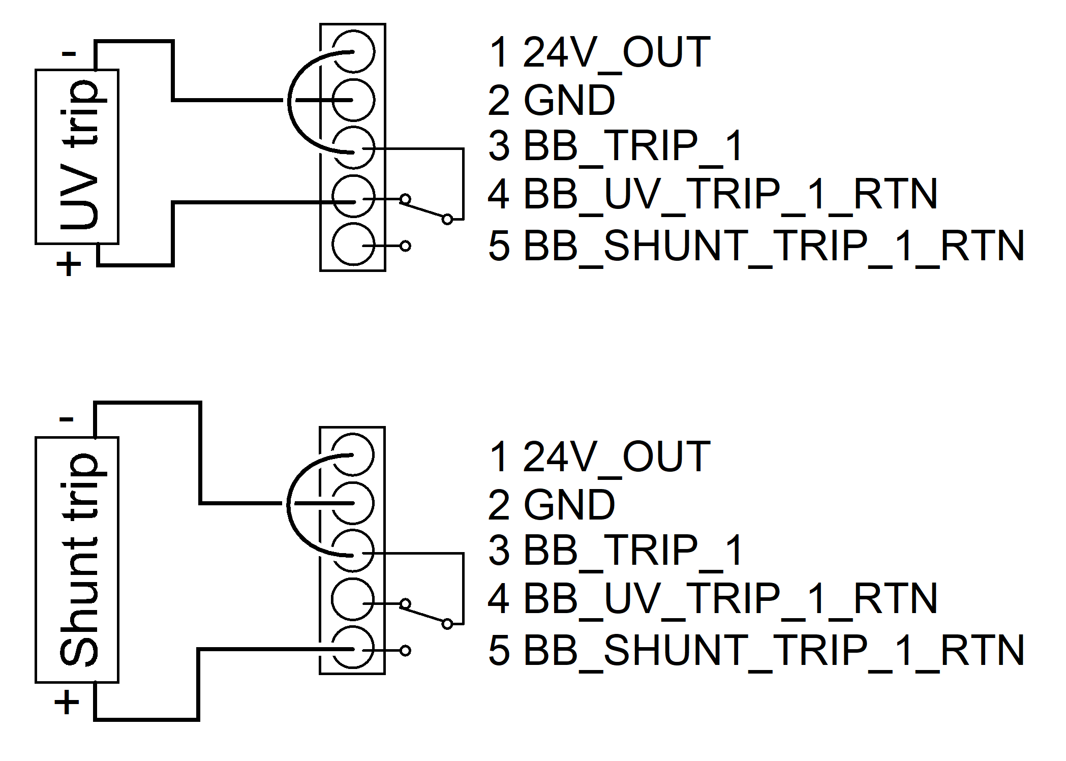
- Connect the signal cables from the battery disconnect device(s)
in your battery solution for shunt trip or undervoltage (UV) trip
connection to the UPS. Follow the illustration for connection with
internal or external 24 VDC supply. The UPS can connect to and monitor
up to four battery disconnect devices.
- Connect battery disconnect device 1 to terminal J8305 in the UPS.
- Connect battery disconnect device 2 to terminal J8306 in the UPS.
- Connect battery disconnect device 3 to terminal J8307 in the UPS.
- Connect battery disconnect device 4 to terminal J8308 in the UPS.
Battery Disconnect Device Trip Connection with Internal 24 VDC Supply
Battery Disconnect Device Trip Connection with External 24 VDC Supply

Supported Shunt
Voltage (V) Current (A) Time (ms) Temperature Recommended cable size* IEC UL/NEC 24 1.6 Continuous 20 °C (68 °F) 0.5 mm2 copper 20 AWG copper 24 10 1300 20 °C (68 °F) 1.5 mm2 copper 16 AWG copper 24 20 200 20 °C (68 °F) 2.5 mm2 copper 13 AWG copper 24 30 60 20 °C (68 °F) 4 mm2 copper 11 AWG copper The cable supplying the shunt trip shall be a jacket cable and rated for 600 VAC. The specifications and recommendations of the shunt trip manufacturer must always be considered when selecting the cable.
- Connect signal cables from AUX switches in your switchgear
to the UPS.

Terminal number Function Connection J8303, 1-2 UOB_RED (redundant AUX switch in unit output disconnect device) Connect to redundant AUX switch in unit output disconnect device UOB. J8303, 3-4 Grid interactive UPS feature: Force UPS into battery operation Connect to normally open (NO) input contact used for grid interactive UPS feature (fast frequency response). Contact Schneider Electric for details and setup of this feature. J8303, 5-6 SIB (system isolation disconnect device) Connect to normally open (NO) AUX switch in system isolation disconnect device SIB for parallel system. SIB must contain an AUX switch for each connected UPS. J8304, 1-2 BB1 (battery disconnect device 1) Connect to normally open (NO) AUX switch in battery disconnect device number 1. J8304, 3-4 BB2 (battery disconnect device 2) Connect to normally open (NO) AUX switch in battery disconnect device number 2. J8304, 5-6 BB3 (battery disconnect device 3) Connect to normally open (NO) AUX switch in battery disconnect device number 3. J8304, 7-8 BB4 (battery disconnect device 4) Connect to normally open (NO) AUX switch in battery disconnect device number 4. J8302, 7-8 UOB (unit output disconnect device) Connect to normally open (NO) AUX switch in unit output disconnect device UOB. J8302, 3-4 SSIB (static switch input disconnect device) Connect to normally open (NO) AUX switch in static switch input disconnect device SSIB. SSIB must contain an AUX switch for each connected UPS. J8302, 1-2 UIB (unit input disconnect device) Connect to normally open (NO) AUX switch in unit input disconnect device UIB. UIB must contain an AUX switch for each connected UPS. J8302, 5-6 MBB (maintenance bypass disconnect device) Connect to normally closed (NC) AUX switch in maintenance bypass disconnect device MBB. MBB must contain an AUX switch for each connected UPS. J8300, 1-5 EXT BF (external backfeed disconnect device) See Backfeed Protection. J8301, 1-2 EXT BF RED (redundant power supply for external backfeed disconnect device) See Backfeed Protection.