Ethernet Architectures
Introduction
Choosing an Ethernet topology depends on the requirements of the communication architecture:
-
A star communication network offers an architecture with high dependability.
-
A daisy-chain architecture offers a competitive architecture.
Ethernet High Dependability
In the case of Ethernet high dependability, the architecture is event tolerant.
A high dependability Ethernet architecture is based around a event tolerant backbone ring (either optic fiber or copper) to which all the subsystems are connected via managed switches.
This communication architecture solution increases process availability with a high level of redundancy and performance. It is entirely based on devices with native Ethernet TCP or Ethernet/IP protocols, for power and motor management architecture. This architecture embeds the best performance for supporting RSTP protocols, and covers all detected events in communication.
This solution also allows power monitoring facilities with new communicating devices supporting web servers.
Star Communication Architecture
The star communication architecture has a high level of dependability.
A star network is a Local Area Network (LAN) in which all nodes (that is, devices) are directly connected to a common central node (that is, the managed switch). Every device is indirectly connected to every other through the managed switch. In a star network, a cable problem isolates the device that links it to the switch, but only that device is isolated. All the other devices continue to function normally, except that they are not able to communicate with the isolated device.
If any device is inoperative, none of the other devices are affected. But if the switch is inoperative, the entire network suffers degraded performance or complete detected failure.
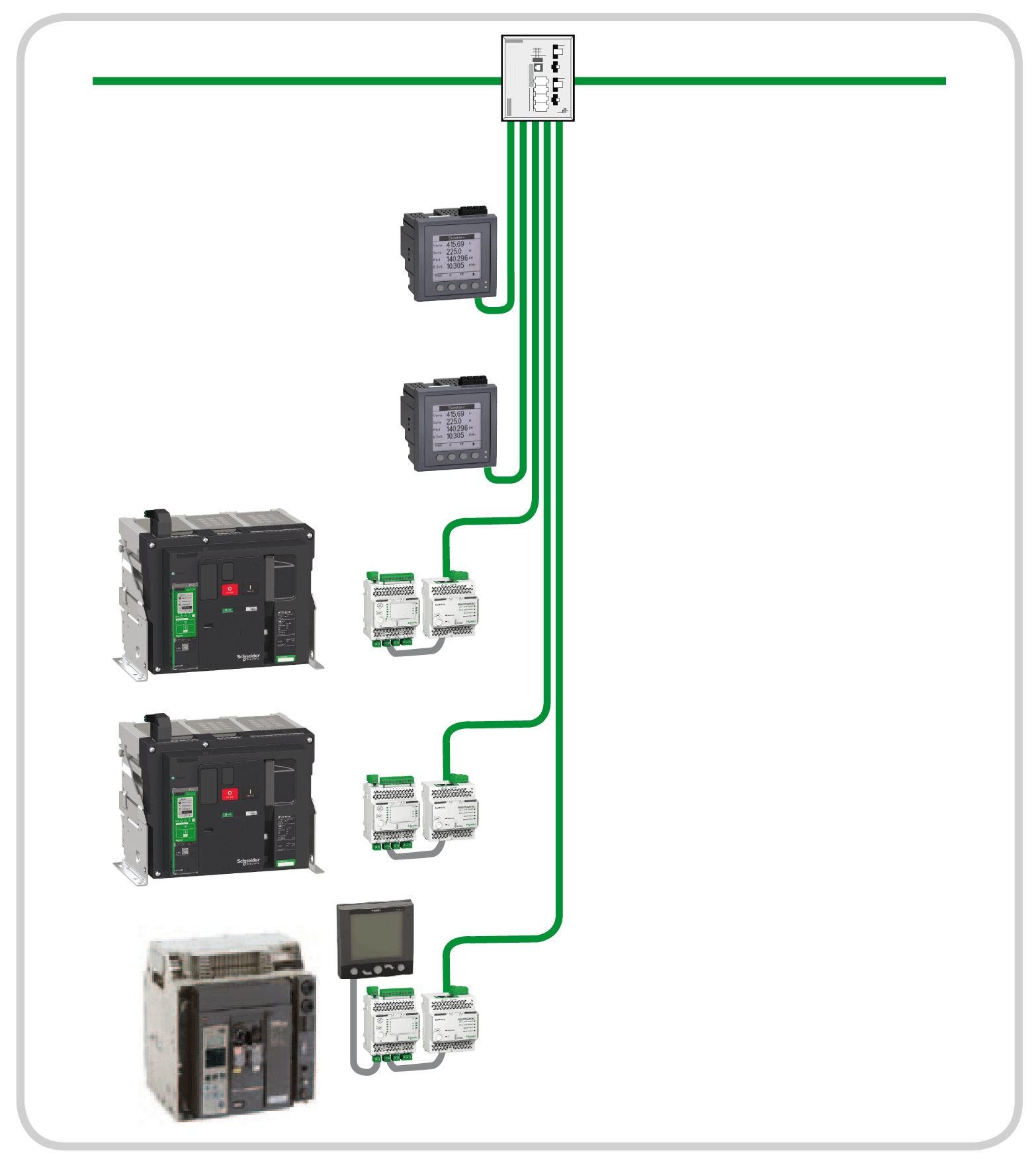
The example of the star architecture in the following diagram uses IFE interfaces and power meters which are directly connected to the managed switch. This switch is the central node and provides a common connection point for all devices (peripheral nodes) connected in the star.
The star topology reduces the damage caused by line problem. If this occurs, a problem of a transmission line linking any peripheral node to the central node results in the isolation of that peripheral node from all others, but the remaining systems are unaffected.
The managed switch makes the connection between the devices and the HiPER-Ring managed backbone.
The following table presents the benefits of a star architecture for the user:
|
User values |
Characteristics |
Validity in the architecture |
Benefit for the user |
|---|---|---|---|
|
Dependability |
Tolerant to first switch problem |
– |
✔ |
|
Tolerant to first node problem |
✔ |
||
|
Tolerant to second node problem |
✔ |
||
|
Tolerant to several node problems |
✔ |
||
|
One or more common modes |
– |
||
|
Additional problem modes |
✔ |
||
|
Operability |
Withdrawability of one functional unit |
✔ |
✔ |
|
Withdrawability of two functional units |
✔ |
||
|
Withdrawability of several functional units |
✔ |
Ethernet Competitive Architecture
A competitive architecture is an optimized and recommended reference for some dedicated applications where redundancy is not required.
Daisy Chain Communication Architecture
A daisy chain communication architecture is a competitive architecture.
A daisy chain is an interconnection of devices, peripherals, or network nodes in series, one after another. It is connected to the bus backbone via an unmanaged switch.
The daisy chain is a simple architecture, but devices must have two Ethernet communication ports.
If any device becomes inoperative, or if a cable problem occurs, it will isolate devices that are connected after the problem. The remaining devices (between the switch and the cable problem) continue to operate normally, but they are not able to communicate with the isolated devices.
But if the switch is inoperative, the entire daisy chain network suffers a complete detected failure.
This type of architecture for connecting devices is recommended in the case of competitive global architecture.
The following table presents the benefits of a daisy-chain architecture for the user:
|
User values |
Characteristics |
Validity in the architecture |
Benefit for the user |
|---|---|---|---|
|
Dependability |
Tolerant to first switch problem |
– |
– |
|
Tolerant to first node problem |
– |
||
|
Tolerant to second node problem |
– |
||
|
Tolerant to several nodes problems |
– |
||
|
One or more common modes |
– |
||
|
Additional problem modes |
– |
||
|
Operability |
Withdrawability of one functional unit |
✔ |
✔ |
|
Withdrawability of two functional units |
✔ |
||
|
Withdrawability of several functional units |
✔ |


