NVE58348-02

Mounting the Supports

Rules for Mounting the Supports

Follow these general rules for mounting the supports:

Figure showing the use of a transverse stay for a fixed point

  • Before mounting the supports, note their types and intended locations.

  • No element must be left unsupported.

  • For easier levelling, always use two supports for each element.

  • A support must never coincide with a joint block.

  • Always maintain a distance of at least 250 mm between the center of the joint block and the support.

  • The maximum distance between horizontal supports is 1.5 m for straight busbar runs.

  • When using fixed-point supports, the use of supporting structures with transverse stays is recommended, as shown in the figure on the left.

  • The minimum distances between the installed elements, walls, and ceilings must be taken into account while installing the supports, as shown in the following figures.

Figure showing recommended distances between a joint block and a support, and between two supports. The orientations shown are widthwise (left) and edgewise (right).

Figure showing minimum distances between the elements and walls in a vertical installation (left), and between the elements, walls and the ceiling in a horizontal installation (right)

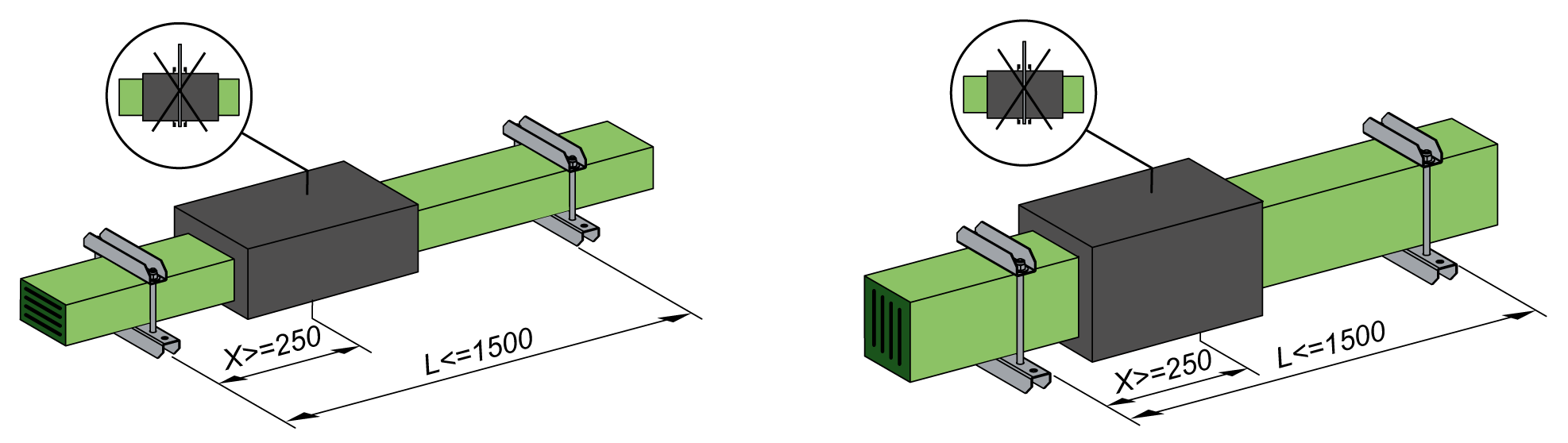
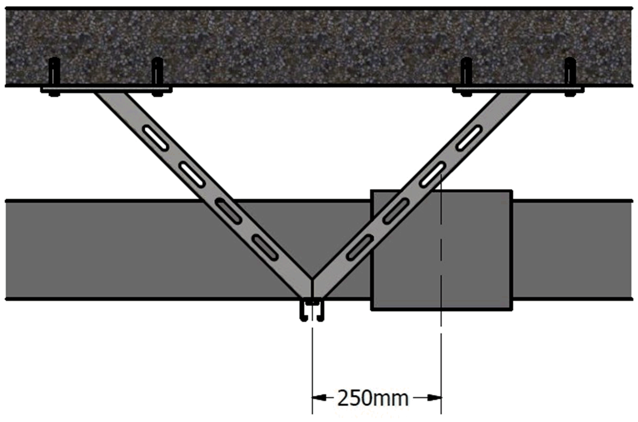
For horizontal installation the minimum gap between ceiling and busway should be 150 mm, however the recommended gap should be 500 mm to ease assembly of junctions.

Terminal Elements, Vertical Branches, Elbows, and Z Shaped Elements (Zeds)

Follow these rules for mounting supports intended for terminal elements, vertical branches, elbows, and zeds:

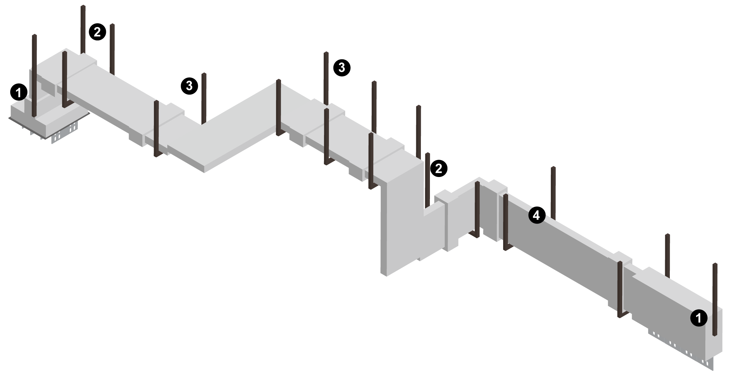
  • Terminals (1) must be fixed by their own supports and not be supported by transformers or switchboards.

  • Vertical branches (2) must be always supported as close as possible to the elbow angle.

  • Elbows and zeds (3) must be supported individually.

  • Supports must be installed close to junctions (4).

Mounting the Supports

This table explains how to mount the supports:

Step

Action

1

First check that the installation plan and all the rules regarding support installation described in Layout and Supports have been followed.

2

Mount the supports on to the support structures of the building. Fix supports with bolts and anchors.

3

Level and align the supports using the levelling instrument.

NOTE: These instructions only apply to accessories supplied by Schneider Electric. For further information, refer to the relevant catalogue or extra technical specifications.

It is beyond the scope of this manual to document the number of different on-site conditions that may exist. Therefore, it is recommended that installation experts evaluate the site conditions.

QR Code is a registered trademark of DENSO WAVE INCORPORATED in Japan and other countries.

Was this helpful?