Connect the Power Cables
| NOTICE |
|---|
|
Risk of equipment damage
To ensure correct load sharing in bypass operation in
a parallel system:
Failure to follow these instructions can result in equipment damage.
|
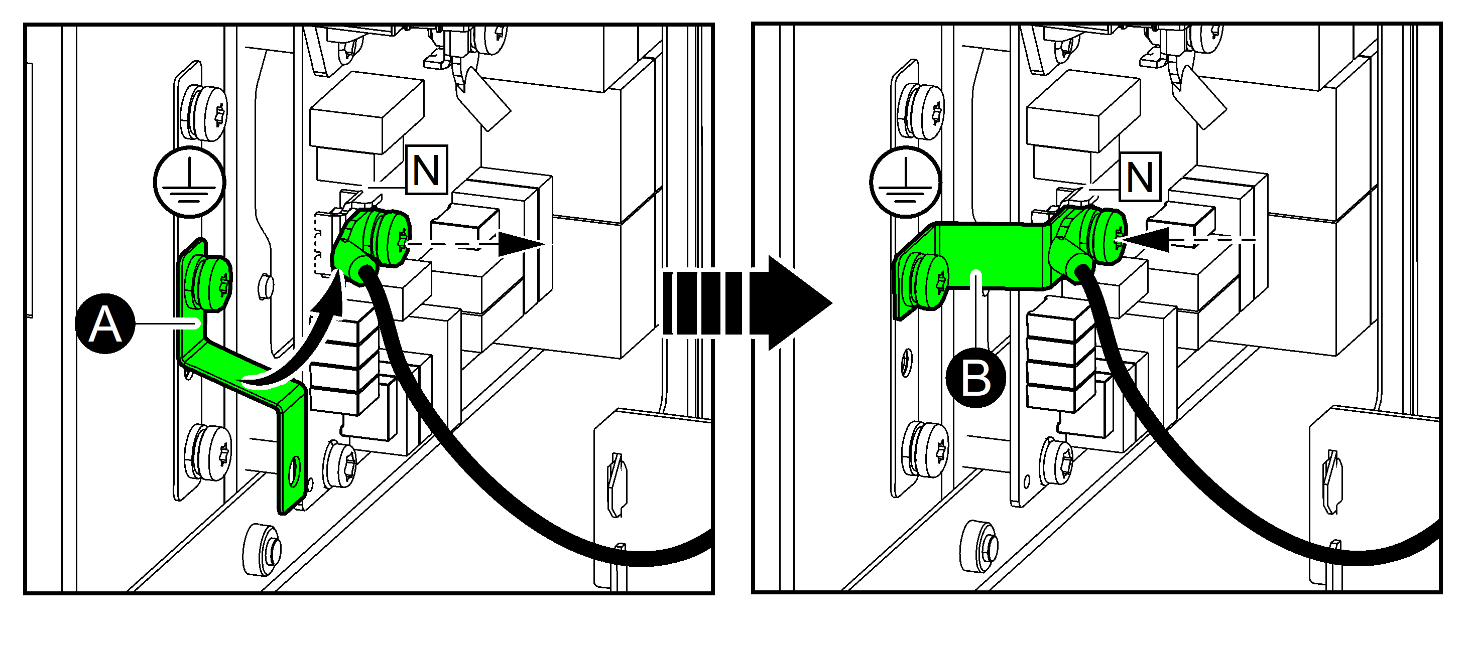
- Only for TN-C/3-wire earthing system: Move the bonding busbar from position (A) to position (B) to connect the N busbar to the G/PE busbar.
- Only for dual mains system: Remove the indicated single mains jumper cables located behind the output/bypass terminals.
- Connect the power cables as shown:
- Connect the equipment grounding conductor/PE cables.
- Connect the input cables.
- Only for dual mains system: Connect the bypass cables.
- Connect the output cables.
NOTE: Torque the insulated ferrules to 3.7 Nm (2.7 lb-ft / 32.7 lb-in). CAUTIONRisk of equipment damageCheck the fastening of the cable lugs/insulated ferrules. If the cable lugs/insulated ferrules move due to pulling on cables, the bolt/screw can become loose.Failure to follow these instructions can result in injury or equipment damage.
 - Reinstall the right rear plate.
- Reinstall the left rear gland plate on the UPS.


