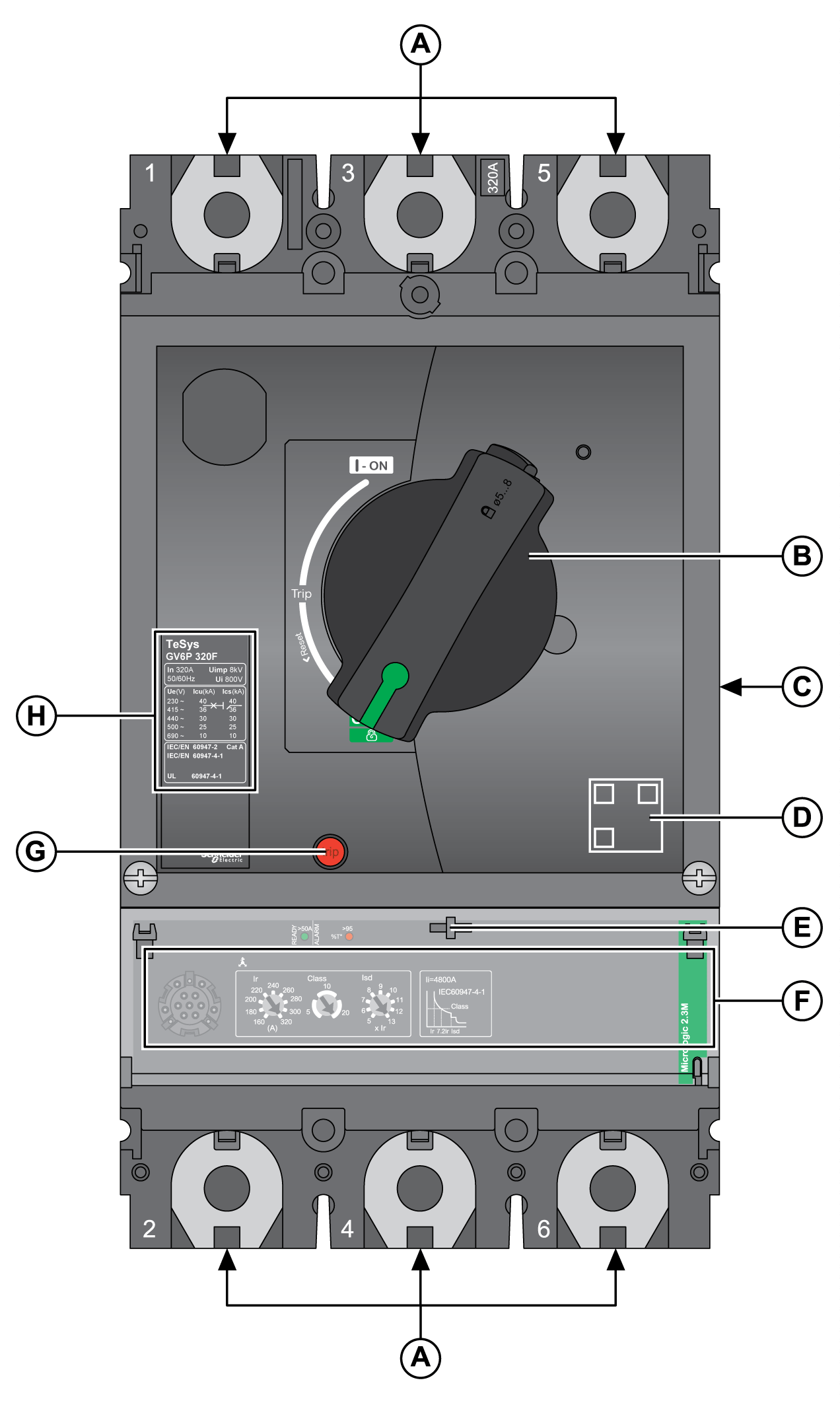
Device Overview
Device Description
TeSys GV5 / GV6 devices are equipped with direct rotary handles as standard.
The device operating controls, operation indicators, settings, and locking mechanisms for the direct rotary handle are located on the front of the device.
There are two models of rotary handle:
-
Black handle for standard applications
-
Red handle on yellow bezel for machine control applications
QR code
Scan the QR code to get additional information about the device from the Schneider Electric website. To scan the QR code, use a smartphone that is equipped with a camera and installed with a QR code reader.
Devices with Extended Rotary Handle
For devices with an extended rotary handle:
-
The device operating controls are located on the front cover.
-
The operation indicators and settings are accessible when the door is open.
-
The locking mechanisms are located on the front cover (door closed).
There are two models of extended rotary handle:
-
Black handle for standard applications
-
Red handle on yellow bezel for machine control applications
Rating Plate
The rating plate on the front of the device identifies the device and its characteristics. The rating plate depends on the breaking performances.
TeSys GV5 Accessories
|
Legend |
Accessory |
Instruction sheet reference |
|---|---|---|
|
A |
Terminal shield |
|
|
B |
Interphase barrier |
|
|
C |
Insulating screen (45 mm / 1.8 in) |
|
|
D |
Steel connector (1.5–95 mm² / 16-4/0 AWG) |
|
|
E |
Aluminum connectors for one conductor (25-185 mm² / 4 AWG-350 kcmil) |
|
|
F |
Aluminum connector for one conductor (120-240 mm² / 250-450 kcmil) |
|
|
G |
Spreaders (35-45 mm / 1.4-1.8 in) |
|
|
H |
Extended rotary handle |
|
|
I |
Open door shaft operator |
|
|
J |
MCC conversion accessory |
|
|
K |
Spare direct rotary handle |
|
|
L |
OF, SD, or SDE indication contacts |
|
|
M |
SDE adapter |
|
|
N |
MN/UVR or MX/SHT voltage releases |
|
|
O |
SDTAM thermal fault module |
|
|
P |
Combination kit for contactor |
TeSys GV6 Accessories
|
Legend |
Accessory |
Instruction sheet reference |
|---|---|---|
|
A |
Terminal shield (45 mm / 1.77 in) |
|
|
B |
Terminal shield (52.5 mm / 2.07 in) |
|
|
C |
Interphase barrier |
|
|
D |
Insulating screen (70 mm / 2.76 in) |
|
|
E |
Aluminum connector for one conductor (35-300 mm² / 2 AWG-600 kcmil) |
|
|
F |
Aluminum connector for two conductors (35-240 mm² / 2 AWG-500 kcmil) |
|
|
G |
Spreader (52.5 mm / 2.07 in) |
|
|
H |
Spreader (70 mm / 2.76 in) |
|
|
I |
Extended rotary handle |
|
|
J |
Open door shaft operator |
|
|
K |
MCC conversion accessory |
|
|
L |
Spare direct rotary handle |
|
|
M |
SDTAM thermal fault module |
|
|
N |
OF, SD, or SDE indication contacts |
|
|
O |
MN/UVR or MX/SHT voltage releases |
Sealing Accessories
Use sealing accessories to prevent device operations.
|
Seal type |
Helps to prevent |
Seal image |
|---|---|---|
|
Seal for front cover mounting screw |
|
|
|
Seal for transparent protective cover of the trip unit |
Altering trip unit settings |
|
|
Seal for mounting screw for terminal shields |
Accessing the power connection (protection against direct contact) |
For more information about the installation of sealing accessories, consult the instruction sheet on the Schneider Electric website: GHD16296AA.


