Hardware Description
Description
A 24 Vdc power supply terminal block
B Digital input terminal block: six inputs, three commons, and one shield
C Six input status LEDs
D Three output status LEDs
E I/O identification labels
F Sealable transparent cover
G Digital output terminal blocks
H ULP status LED
I Test/reset button (accessible with cover closed)
J Setting locking pad
K Application rotary switch: 1 to 9
L Switch for IO module addressing (IO module 1 or IO module 2)
M Two RJ45 ULP ports
N Grounding connection
Mounting
The IO module mounts on a DIN rail.
Power Supply
The IO module must always be supplied with 24 Vdc.
It is recommended to use an UL listed and recognized limited voltage and current or a class 2 power supply with a 24 Vdc, 3 A maximum.
Application Rotary Switch
The application rotary switch enables the selection of a predefined application. It has nine positions and each position is assigned to a predefined application. The factory-set position of the switch is predefined as application 1.
Setting Locking Pad
The setting locking pad on the front panel of the IO module enables the setting of the IO module by the EcoStruxure Power Commission software.
-
If the arrow points to the open padlock (factory setting), loading of the configuration file from the EcoStruxure Power Commission software is allowed.
-
If the arrow points to the closed padlock, loading of the configuration file from the EcoStruxure Power Commission software is not allowed.
Test/Reset Button
The test/reset button has three functions, according to how long the button is pressed.
|
Time Range |
Function |
|---|---|
|
0.25–1s |
Reset the alarms in manual reset mode. |
|
1–5 s |
Test the ULP modules connected in the IMU. |
|
5–15 s |
Validate the application selected through the application rotary switch. |
ULP Status LED
The ULP Status LED describes the mode of the ULP module.
|
ULP Status LED |
Mode |
Action |
|---|---|---|
|
Nominal |
None |
|
|
Conflict |
Remove modules with duplicate function. |
|
|
Degraded |
Replace IO module at the next maintenance operation. |
|
|
Test |
None |
|
|
Non-critical firmware discrepancy |
Use the EcoStruxure Power Commission software to check the firmware and hardware compatibility and follow the recommended actions. Update module firmware if necessary Firmware Update. |
|
|
Non-critical hardware discrepancy |
||
|
Configuration discrepancy |
Install missing features. |
|
|
Critical firmware discrepancy |
Use the EcoStruxure Power Commission software to check the firmware and hardware compatibility and follow the recommended actions. Update module firmware if necessary Firmware Update. |
|
|
Critical hardware discrepancy |
||
|
Stop |
Replace IO module. |
|
|
Power OFF |
Check power supply. |
For more information, refer to Troubleshooting.
Switch for IO Module Addressing (IO Module 1 or IO Module 2)
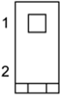
When two IO modules are connected in the same ULP network used in one IMU, the two IO modules are differentiated by the position of the DIP switch located on the bottom of the IO module:
|
Switch Postition |
Description |
|---|---|
|
DIP switch on position 1 for IO module 1 (factory setting) |
|
|
DIP switch on position 2 for IO module 2 |
The consistency of the configuration of both IO modules is checked. If the DIP switch of both IO modules is in the same position, an IO module in ERROR mode alarm is generated.


