Wiring - Ground Current Sensors
Ground Current Sensor Installation
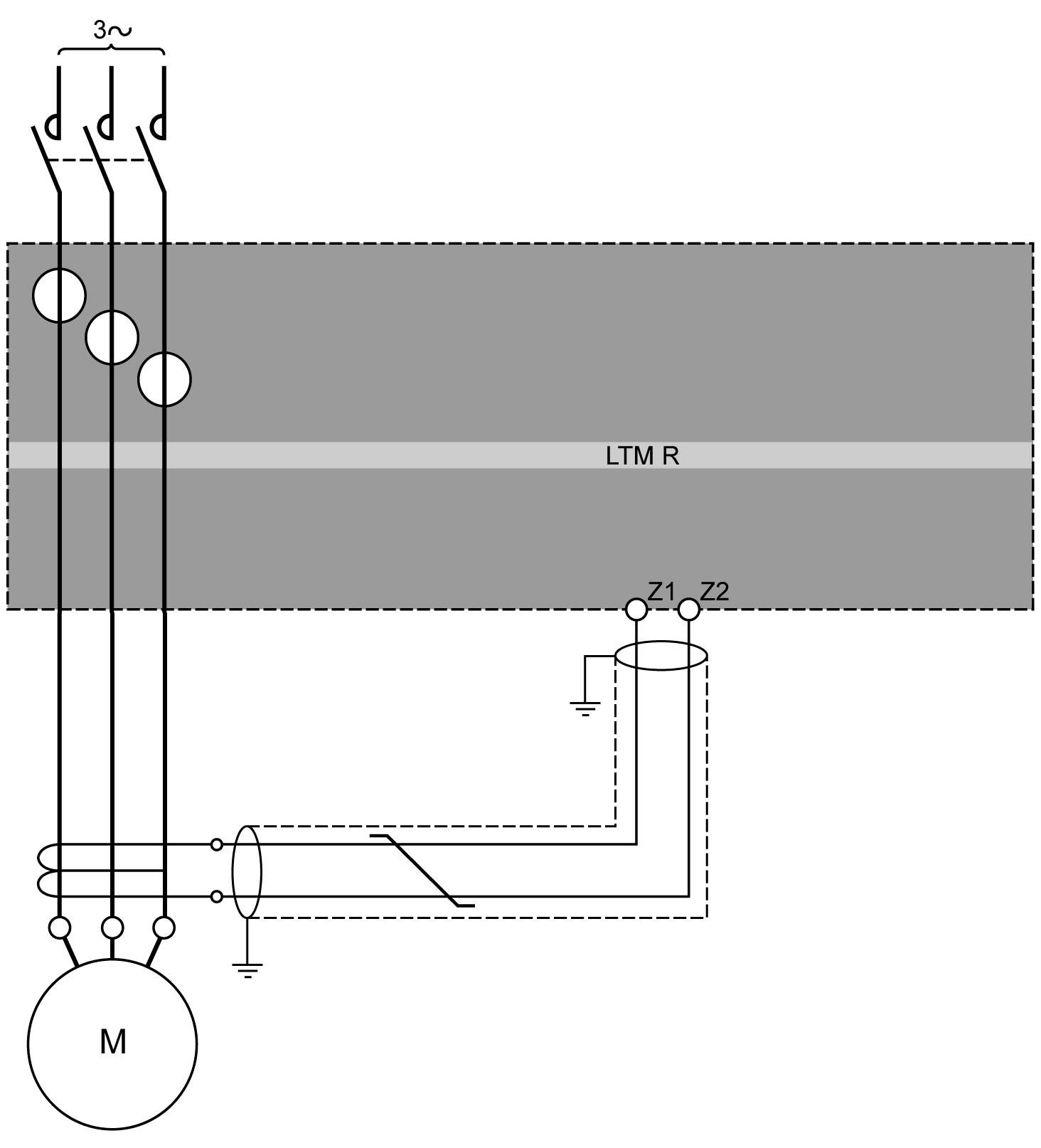
The following diagram shows a typical LTMR controller installation using a ground current sensor (GFCT):
GFCTs are specified with a transformation ratio. The ratio of the GFCT is the ratio of the ground trip current sensed to the current which it outputs.
To enable the controller to correctly measure the actual ground trip current flowing in the circuit, set the following parameters:
-
Ground CT Primary (the first number of the GFCT ratio)
-
Ground CT Secondary (the second number of the GFCT ratio)
For a description of GFCT characteristics, refer to the TeSys T LTMR Motor Management Controller User Guide.
Ground Current Sensor Wiring
The external ground current sensor (GFCT) must be connected to the LTMR controller terminals Z1 and Z2 using a shielded twisted pair cable. The shield must be connected to the earth at both ends by the shortest possible connections.


