Mounting
Overview
This section describes how to mount the LTMR controller and the LTME expansion module on a DIN rail, a solid mounting plate, or a pre-slotted mounting plate (known as a TE plate), such as a Telequick™ plate. It also describes the accessories needed for mounting, as well as how to remove each component.
Reminder: The LTMR controller and its LTME expansion module must be mounted side by side, with the LTME expansion module on the left side of the LTMR controller, connected by the LTMCC004 connecting jumper Assembly.
Mounting on DIN Rails
You can mount the controller and the expansion module on a 35 mm (1.38 in.) DIN rail with a thickness of 1.35 mm (0.05 in.) and 0.75 mm (0.02 in.). When mounted, the controller mounting feet may not extend beyond the controller dimensions. To mount the controller:
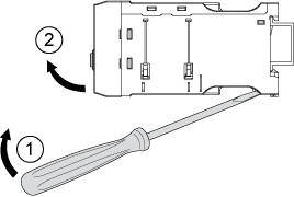
Removing from DIN Rails
To remove the controller from the DIN rail:
Mounting on a Solid Mounting Plate
You can mount the controller and the expansion module on a metal mounting plate using ST2.9 steel tapping screws: four for the controller and two for the expansion module. The thickness of the mounting plate must not exceed 7 mm (0.275 in.). When mounted, the controller mounting feet may extend beyond the controller dimensions by 8 mm (0.3 in.) in both directions. To mount the controller and the expansion module on a mounting plate:
|
Step |
Action |
|---|---|
|
1 |
Locate the four mounting holes at each corner of the controller and the two mounting holes on the expansion module. |
|
2 |
Position the controller and expansion module on the mounting plate, making sure to leave enough space for the clearance zone Dimensions. |
|
3 |
Insert each of the six tapping screws. |
|
4 |
Use a screwdriver to tighten each screw and secure the controller and the expansion module in place. Torque to 1 N•m (8.8 lb-in). |
Mounting on a TE Plate
You can mount the controller and the expansion module on a TE plate, such as Telequick, using six mounting clips (AF1 EA4). When mounted, the controller mounting feet may extend beyond the controller dimensions by 8 mm (0.3 in.) in both directions. To mount the controller on Telequick:
|
Step |
Action |
|---|---|
|
1 |
Attach the six mounting clips to Telequick, as shown in the diagram below. The rounded edge should face upwards for the top clips, and downwards for the bottom clips. |
|
2 |
Position the controller and expansion module on the clips so that the holes in the clips and the holes in the controller and expansion module align. Insert the screws in the holes and turn them slightly. |
|
3 |
When the controller and expansion module are properly positioned, tighten first the bottom screws, then the top screws using a screwdriver. Torque to 1 N•m (8.8 lb-in). |
Operating Position
You can mount the controller and the expansion module at an angle of up to 90 degrees perpendicular to the normal vertical mounting plane.


