
Phase-Cut Dimming
A phase cut (also known as phase control) dimmer adjusts the brightness of the connected load by varying the portion of the mains AC waveform that is passed through the connected load.
In a 50 Hz system, a full mains cycle takes 20 milliseconds (ms), which consists of a 10 ms positive half-cycle and a 10 ms negative half-cycle.
At the beginning of the cycle, the mains voltage is zero (zero crossing), it then rises to reach its peak value (~340 V peak in a 240 V rms system) after 5 ms, before reducing again to zero at 10 ms. The cycle then repeats with the opposite polarity.
Conduction Time
The portion of the 10 ms half-cycle time for which the dimmer passes power to the load is called the conduction time, and might be expressed in milliseconds (ms) or microseconds (μs) where 1 ms = 1000 μs.
Leading Edge (LE) Dimming
Older Dimmer designs used an electronic switching device called a Triac. A triac can be turned ON at any point in the mains cycle, but once turned ON, they cannot be turned OFF without reducing the load current to zero. Due to this limitation, triac dimmers can only perform Leading Edge (LE) phase control, where the triac turns the power to the load on part way through the cycle and it then remains ON until the current drops to zero as the voltage drops to zero.
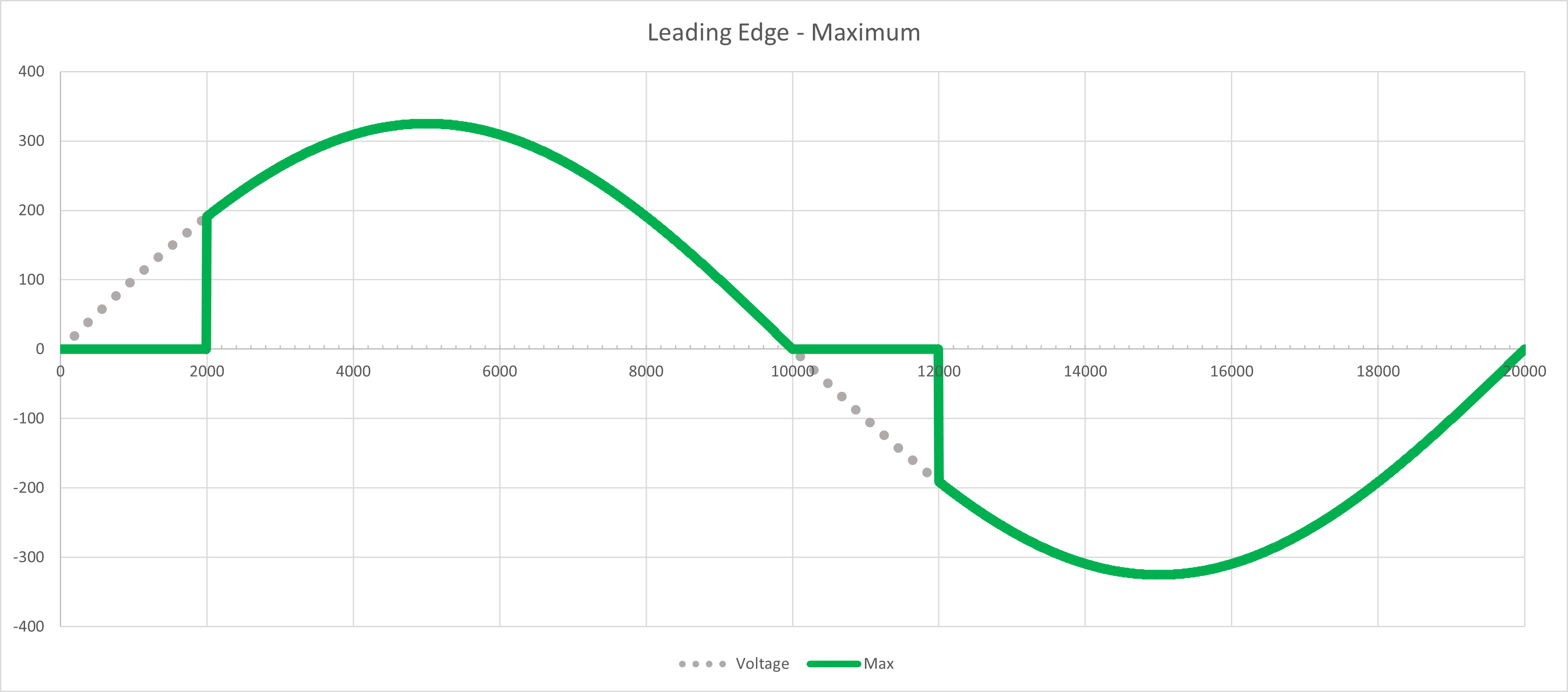
To set a high brightness, the triac is turned on right at the start of the cycle, shortly after the zero crossing, and then allows power through the load for the whole cycle.
The diagram below shows the resulting waveform for a Leading Edge dimmer set to maximum where the maximum conduction is 8 ms. In the positive half-cycle of the mains, the triac remains off until turning on at 2 ms after zero crossing. It then remains on for the 8 ms remaining until the zero crossing at 10 ms. The triac remains off until 2 ms after the zero crossing, when it turns on and remains on for 8 ms until the next zero crossing.
To reduce the brightness, the triac is turned on later in the cycle, some time after the zero crossing. The longer the delay, the lower the conduction time, and the lower the brightness.
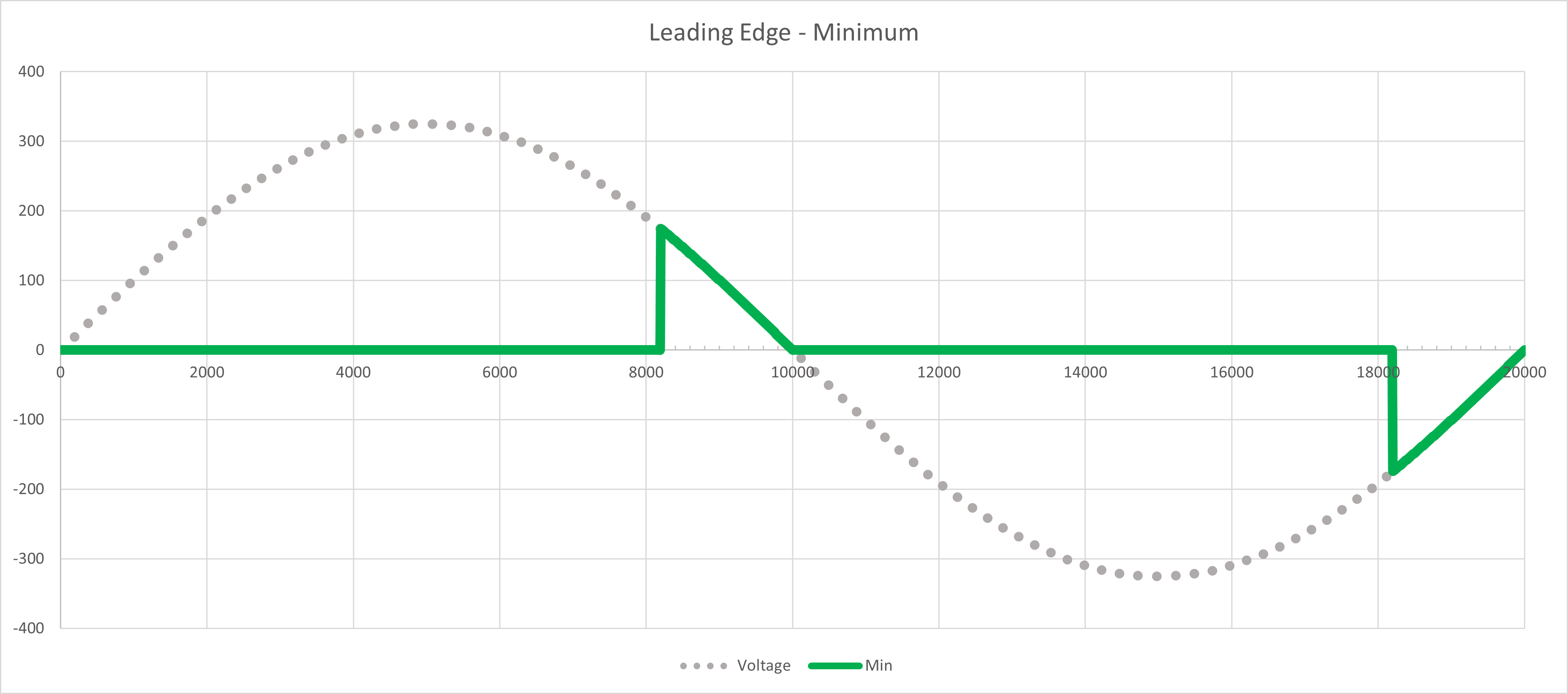
The diagram below shows the resulting waveform for a Leading Edge dimmer set to minimum, where the minimum conduction is 1.8 ms. In the positive half-cycle of the mains, the triac stays off until 8.2 ms after zero crossing and turn on for the remaining 1.8 ms until zero crossing at 10 ms. It repeats the same in the negative half-cycle.
This means depending on where in the cycle the triac turns on, there can be a very large step change in the voltage applied to the load. At 50 % conduction, the step change is equal to the peak of the mains (340 V in a 240 V rms system).
This works well for older style loads such as incandescent lamps and for inductive loads like iron-core low voltage lighting transformers or motors, which naturally limit the inrush current. It is not good for electronic loads such as electronic transformers or LED lighting, which have a capacitance at the input, as this capacitor looks like a short circuit to the triac, causing large inrush current spikes.
Trailing Edge (TE) Dimming
To overcome this problem, instead of a triac, modern dimmers such as the C-Bus Digital Dimmers use a type of electronic switch called a MOSFET. MOSFETs can be turned both ON and OFF at any point in the mains cycle.
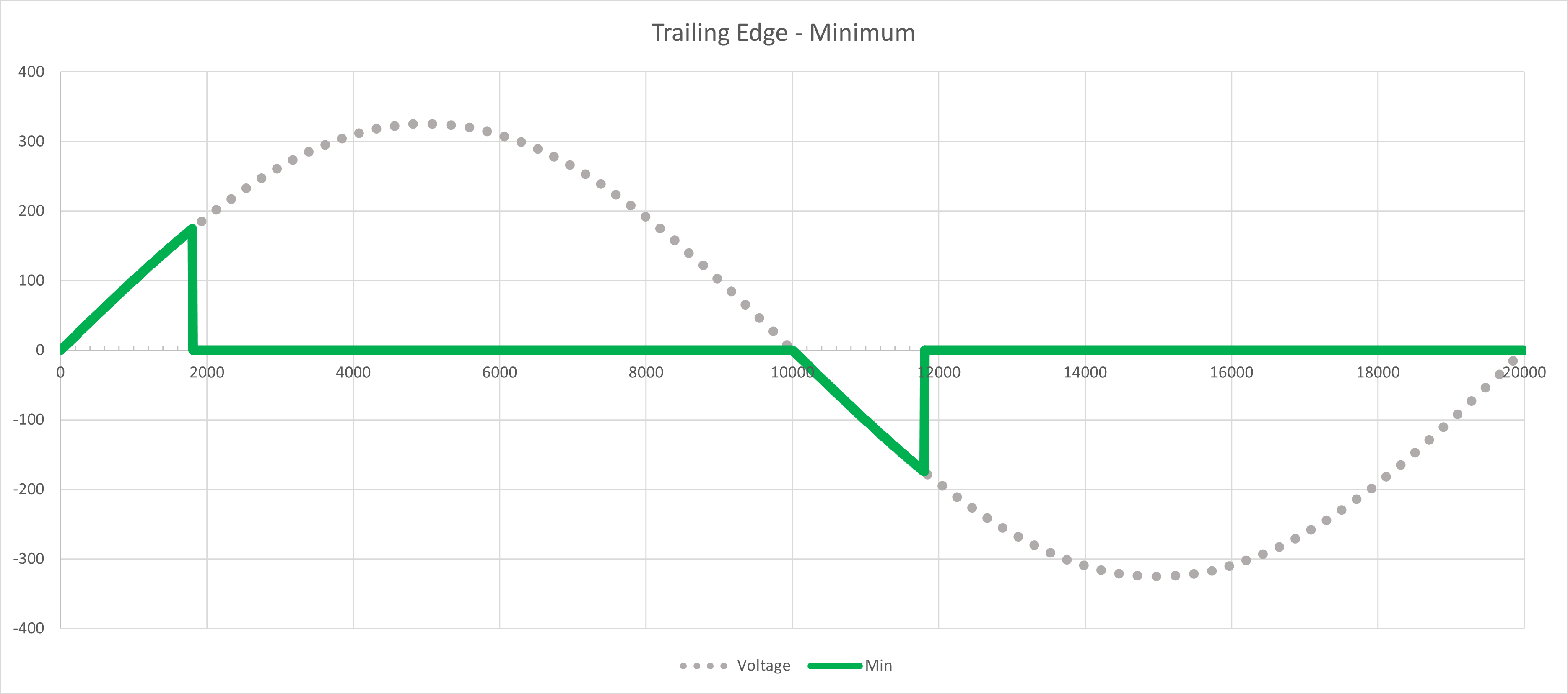
The ability to turn OFF at any point in the mains cycle without waiting for the current to reduce to zero allows MOSFET dimmers to operate in Trailing Edge (TE) phase control, where the power to the load is turned ON at zero crossing, and turned OFF after the desired conduction time.
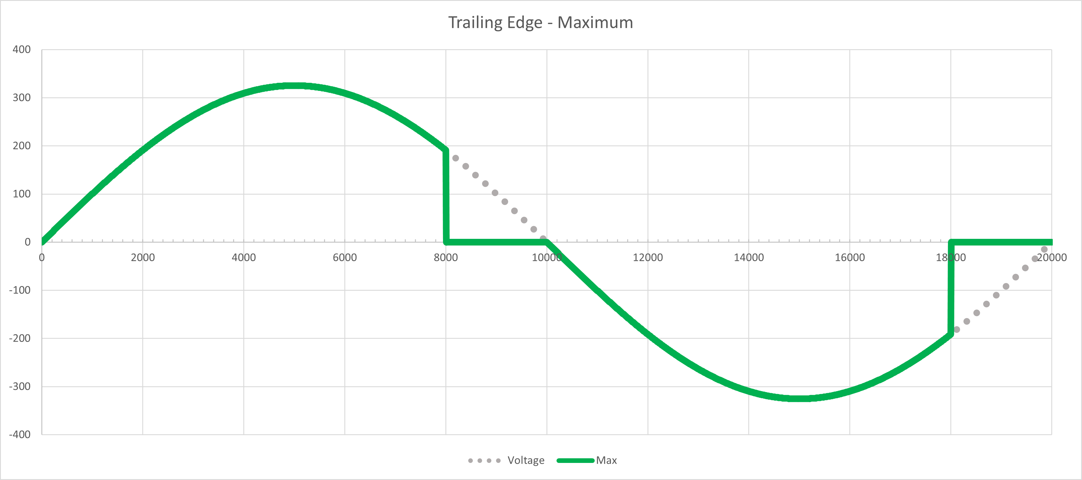
Trailing Edge phase control is ideal for electronic loads like LED lighting, since turning power to the load ON at zero voltage means the inrush current is minimized.
Trailing Edge dimmer is not recommended for inductive loads, since an inductance resists rapid changes in current, resulting in generation of high voltage spikes when the load is switched off.
As a result, Trailing Edge dimmers have a protection mechanism whereby they will shut down if voltage spikes are detected, usually due to an incompatible inductive load being connected.
Universal Dimmers
Since MOSFETs can turn ON and OFF, MOSFET dimmers can also be designed to operate in Leading Edge mode.
A dimmer which can operate in both modes is often referred to as a universal dimmer, which usually start in trailing edge mode (since this is the correct mode for most modern load types), and then switch automatically to leading edge mode if over voltage spikes are detected. Automatic mode selection is not always reliable and often results in erratic or inconsistent behavior.
C-Bus Digital Dimmers
The C-Bus Digital Dimmers are Universal, in that they can operate in either TE or LE mode. However, to avoid the problems with automatic mode selection in traditional Universal dimmers, the correct mode selection is made by the installer, and once set, will not automatically change. The mode for each channel is displayed on, and can be selected from the front panel button for the channel, as well as from the SpaceLogic C-Bus Commission software.
If the mode selected on any channel is unsuitable for the connected load, the channel will simply shut down, and indicate an error via the channel's front panel indicator.