
Measurement Accuracy in Accordance with IEC 61557-12
Measurements and Electrical Parameters Available on the MicroLogic X Control Unit
Based on the measurement of line currents, neutral current, phase-to-phase voltages, and phase-to-neutral voltages, the MicroLogic X control unit displays the following parameters:
-
RMS values of currents and voltages
-
Active, reactive, and apparent powers
-
Active, reactive, and apparent energies
-
Power factor
-
Frequency
-
Unbalance, THD, and THD-R of voltages and currents
Average values are calculated for the main basic electrical parameters.
The maximum and minimum values are time stamped and logged in the MicroLogic X non-volatile memory. They can be reset as follows:
-
On the MicroLogic X display screen
-
With EcoStruxure Power Commission software
-
On the FDM128 display
-
On the FDM121 display
-
By a remote controller using the communication network
-
On the IFE/EIFE webpages
Electrical parameters are refreshed once a second. They can be displayed as follows:
-
On the MicroLogic X display screen, at Measures Menu
-
With the EcoStruxure Power Device app
-
With EcoStruxure Power Commission software
-
On the FDM128 display
-
By a remote controller using the communication network
-
On the IFE/EIFE webpages
The availability of parameters depends on the type of interface used to display data. All parameters are not displayed on all interfaces.
An optional external 24 Vdc supply or VPS module is mandatory to measure and display parameters, including energy counters, for currents below 20% of the rated current In.
The start-up time is the time between when the control unit is energized and the availability of the first measurement. The start-up time is less than or equal to 45 seconds.
Measurement Accuracy
Power and energy metering accuracy in MasterPacT MTZ circuit breakers with MicroLogic X control unit is classified as Class 1, according to IEC 61557-12. This standard specifies performance requirements of measuring and monitoring devices that measure and monitor the electrical parameters within electrical distribution systems. It covers both performance measuring devices with external sensors (PMD-S), such as current and/or voltage transformers, for example, stand-alone power meters, and performance measuring devices with embedded sensors (PMD-D), for example, circuit breakers.
A MasterPacT MTZ circuit breaker, with MicroLogic X control unit and embedded sensors, is a PMD-DD device with Class 1 accuracy, according to IEC 61557-12 for power and energy metering. It complies with the requirements of K70 temperature class and ‘Standard’ humidity and altitude operating conditions, according to table 6 and 7 of IEC 61557-12.
The IEC 61557-12 standard defines the following three levels of uncertainty that need to be checked to establish accuracy class:
A PMD-DD device avoids overall system uncertainty and variation, thanks to its embedded sensors and wiring.
Measured Electrical Parameter Uncertainty
Uncertainty is the estimated percentage by which a measured electrical parameter may differ from the true electrical parameter. In the context of this standard, the total uncertainty of a measured electrical parameter depends on the instrument, the environment, and other elements to be considered.
The following graphic shows the total uncertainty of a measured electrical parameter made by:
-
A PMD-D device, with embedded sensors
-
A PMD-S device, with external sensors
 |
|
|
PMD-D device, with embedded sensors |
PMD-S device, with external sensors |
|
A Uncertainty under reference conditions: Intrinsic uncertainty according to IEC 61557-12 B Variations due to influence quantity: Operating Uncertainty according to IEC 61557-1; Measurement uncertainty according to IEC 61000-4-30 C Overall system uncertainty according to IEC 61557-12 |
|
Intrinsic Uncertainty: IEC 61557-12 Definition
Intrinsic uncertainty is the uncertainty of a measuring instrument when used under reference conditions. In the context of this standard, it is a percentage of the measured electrical parameter defined within the rated range of the measuring instrument.
For MasterPacT MTZ circuit breakers with a MicroLogic X control unit, the main values are current and power factor.
The following table indicates, for different MasterPacT MTZ circuit breakers, the current values for an intrinsic uncertainty less than or equal to 1%:
|
Current values for active power with 1% uncertainty (in A) |
MasterPacT |
|||
|---|---|---|---|---|
|
Description of current value |
Current value |
MTZ1 |
MTZ2 |
MTZ3 |
|
Lowest value of the current at which the circuit breaker starts and continues to register |
Ist = 0.04% Ib |
1.6 A |
1.6 A |
3.2 A |
|
Lowest value of the current for accuracy less than or equal to 1.5% for active power and energy |
5% Ib |
20 A |
20 A |
40 A |
|
Lowest value of the current for accuracy less than or equal to 1% for active power and energy with PF = 1 |
10% Ib |
40 A |
40 A |
80 A |
|
Lowest value of the current for accuracy less than or equal to 1% for active power and energy with PF = 0.5 Inductive to 0.8 Capacitive |
20% Ib |
80 A |
80 A |
160 A |
|
Value of current in accordance with which the relevant performance of a direct connected PMD (PMD Dx) is fixed |
Ib |
400 A |
400 A |
800 A |
|
Highest value of current at which the MasterPacT MTZ circuit breaker meets the uncertainty requirements of this standard |
Imax |
1,600 A x 1.2 |
4,000 A x 1.2 |
6,300 A x 1.2 |
The following graph gives an example of the intrinsic uncertainty for active power and energy versus current for the MasterPacT MTZ2 circuit breaker. It shows that the performance of the MasterPacT MTZ2 circuit breaker is equal to or better than the IEC 61557-12 standard.
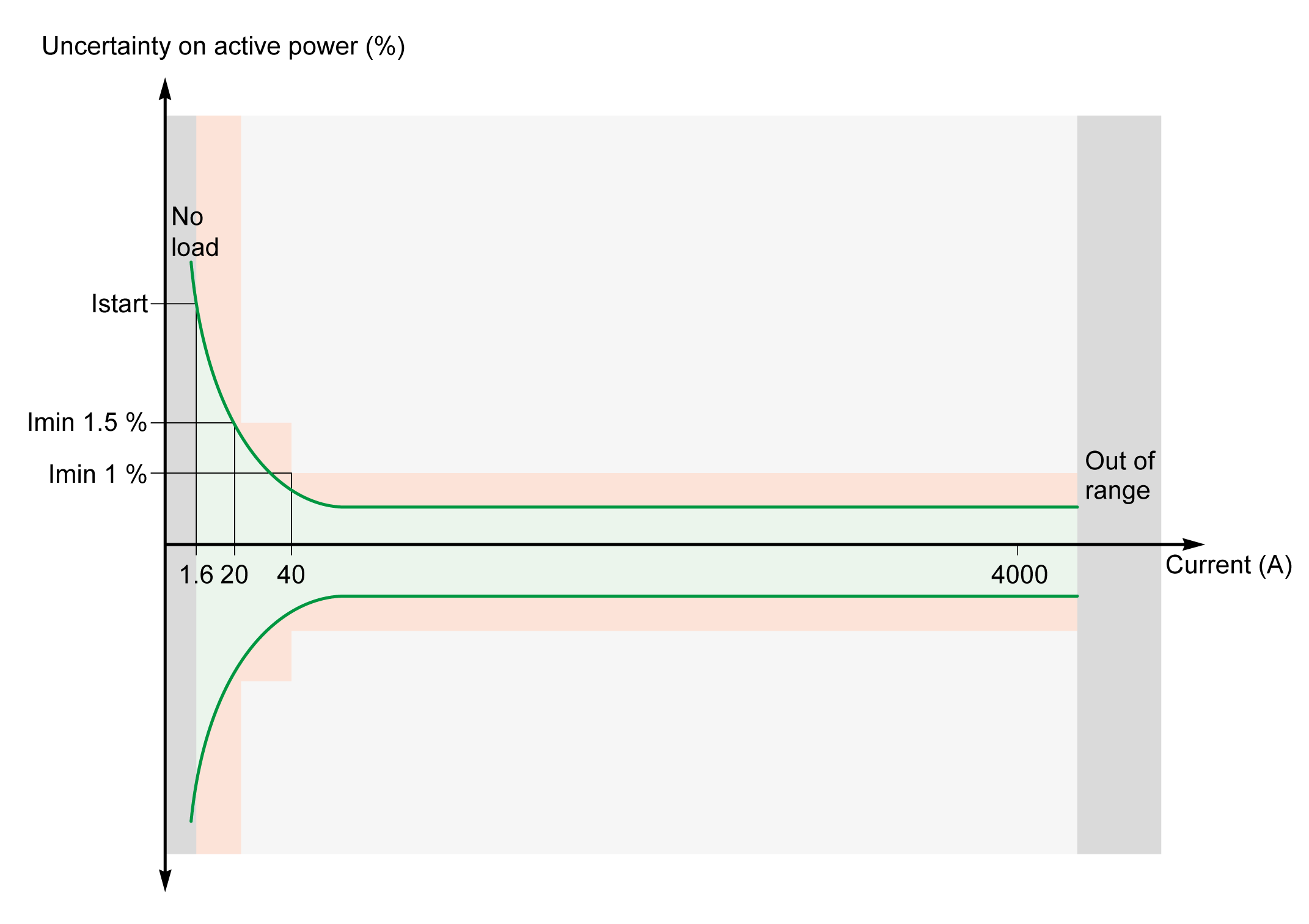
 MasterPacT MTZ2 circuit breaker
 IEC 61557-12 standard
 Out of IEC 61557-12 standard
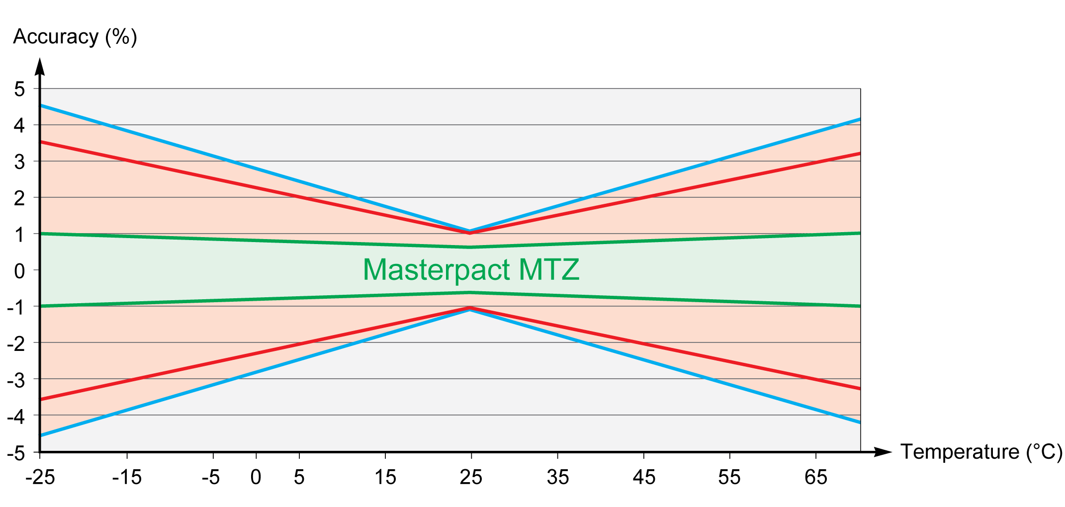
Operating Uncertainty
IEC 61557-12 defines operating uncertainty as uncertainty under the rated operating conditions.
IEC 61557-12 specifies tests and maximum variation of uncertainty according to the following influence quantities:
-
Ambient temperature (T°)
-
Frequency, unbalance, harmonics, EMC
For MasterPacT MTZ circuit breakers with MicroLogic X control unit, the main influence quantity is temperature. MasterPacT MTZ circuit breakers are designed to carry high currents, which induce self-heating. The measurement has been designed to offer high stability in a wide range of temperatures.
Effect of Temperature on MasterPacT MTZ Measurement System
The temperature variation around the internal current transformer and the MicroLogic X control unit, between minimum current and nominal current load can be up to 90 K. The effect of temperature on measurement accuracy has been carefully managed over an operating ambient temperature range of -25 °C (-13 °F) to 70 °C (158 °F).
 |
|
|
|
|


Effect of Electromagnetic Compatibility (EMC) and Other Influence Quantities on MasterPacT MTZ Measurement Performance
MasterPacT MTZ circuit breakers with MicroLogic X control unit offer a high immunity to influence quantities, with a low operating uncertainty for active power, as specified by Class 1, for a wide range of operating conditions.
The following table summarizes standard requirements and MasterPacT MTZ performance regarding influence quantities for active power:
|
Influence quantity |
Table 9 IEC 61557-12 PMD DD Cl 1 additional uncertainty variation tolerance |
MasterPacT MTZ additional uncertainty |
|
|---|---|---|---|
|
Ambient temperature |
PF 1 |
0.05% / K |
< 0.01% / K |
|
PF 0.5 Ind |
0.07% / K |
< 0.01% / K |
|
|
Auxiliary power supply |
24 Vdc ±15% |
0.1% |
0% |
|
Voltage |
PF 1: 80%/120% Vn |
0.7% |
0% |
|
PF 0.5 Ind: 80%/120% Vn |
1% |
0% |
|
|
Frequency |
PF 1: 49–51 Hz/59–61 Hz |
0.5% |
0% |
|
PF 0.5: 49–51 Hz/59–61 Hz |
0.7% |
0% |
|
|
Reversed phase sequence |
1.5% |
0% |
|
|
Voltage unbalance |
0 to 10% |
2% |
0% |
|
Phase missing |
1 or 2 phase missing |
2% |
0% |
|
Harmonics in current and voltage |
10% Vn 5th |
0.8% |
< 0.1% |
|
20% Imax 5th |
|||
|
Odd harmonic in current |
3% |
< 0.1% |
|
|
Sub harmonic in current |
3% |
< 0.1% |
|
|
Common mode voltage rejection |
0–690 Vac/ground |
0.5% |
0% |
|
Permanent ac magnetic induction |
IEC 61326 |
2% |
0% |
|
Electromagnetic RF fields |
IEC 61326 |
2% |
< 1% |
|
Conducted disturbances induced by RF fields |
IEC 61326 |
2% |
< 1% |
Overall System Uncertainty
IEC 61557-12 defines overall system uncertainty as uncertainty including the instrumental uncertainty of several separated instruments (for example, sensors, wires, measuring instruments) under the rated operating conditions.
For MasterPacT MTZ circuit breakers, the sensors are embedded in the device for applications up to 690 Vac phase-to-phase and the overall uncertainty is equal to the operating uncertainty.