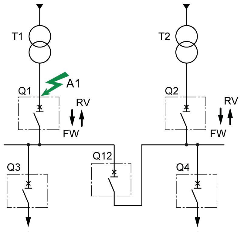
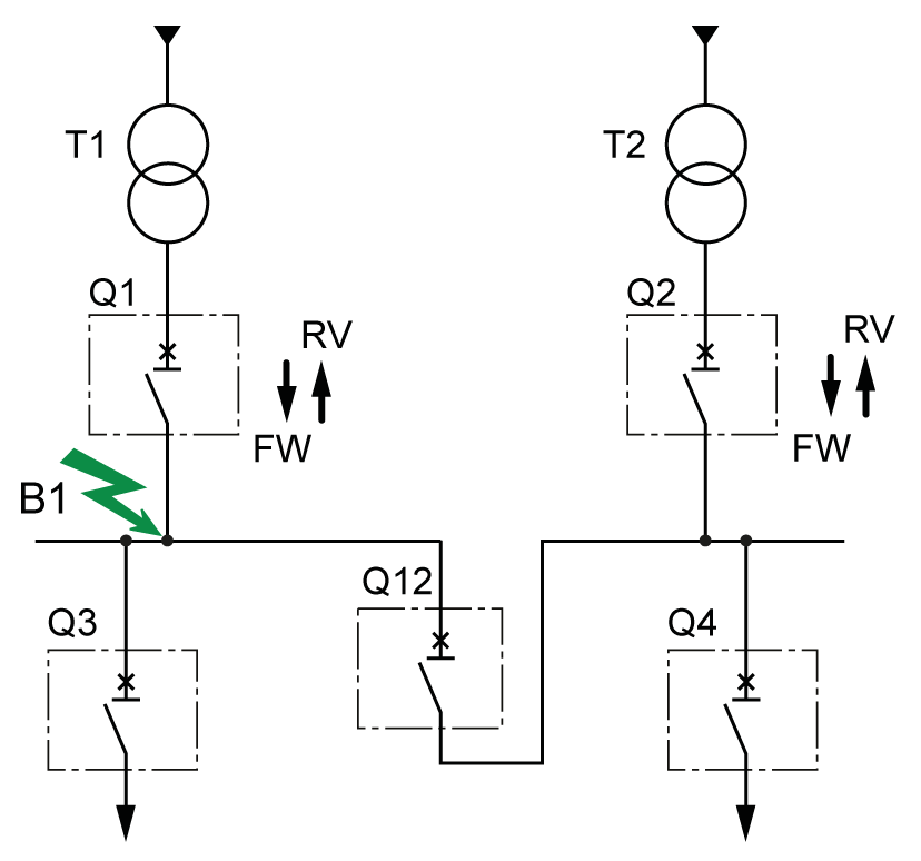
Setting the Directional Overcurrent Protection (ANSI 67)
Setting Guidelines
Directional overcurrent protection is used in conjunction with short-time overcurrent protection. The choice of forward or reverse directional overcurrent protection and time delays (tfw and trv), and the time delay settings of short-time overcurrent protection (tsd) help to protect a power system against short-circuit currents that could circulate in forward and reverse directions.
When directional overcurrent protection is used to trip, instantaneous overcurrent protection (ANSI 50) is usually disabled by setting Ii mode to OFF.
Application on Power System with Multiple Sources in Parallel
Directional overcurrent protection can be applied on a power system with two or more sources running in parallel to increase power availability. The sources can be transformers or generators.
Examples of two power systems are presented, with and without directional overcurrent protection:
-
Two sources running in parallel with no tie circuit breaker.
-
Two sources running in parallel with one tie circuit breaker, with tie circuit breaker normally closed.
|
Hardware configuration |
Protection scheme |
Power availability |
Example applications |
|---|---|---|---|
|
2 sources No tie |
2 circuit breakers without directional overcurrent protection |
– |
Commercial and industrial buildings |
|
2 circuit breakers with directional overcurrent protection |
** |
Commercial and industrial buildings |
|
|
2 sources 1 tie, normally closed |
2 circuit breakers without directional overcurrent protection 1 tie circuit breaker without directional overcurrent protection |
* |
Oil and gas applications Marine applications Data centers |
|
2 circuit breakers with directional overcurrent protection 1 tie circuit breaker without directional overcurrent protection |
*** |
Oil and gas applications Marine applications Data centers |
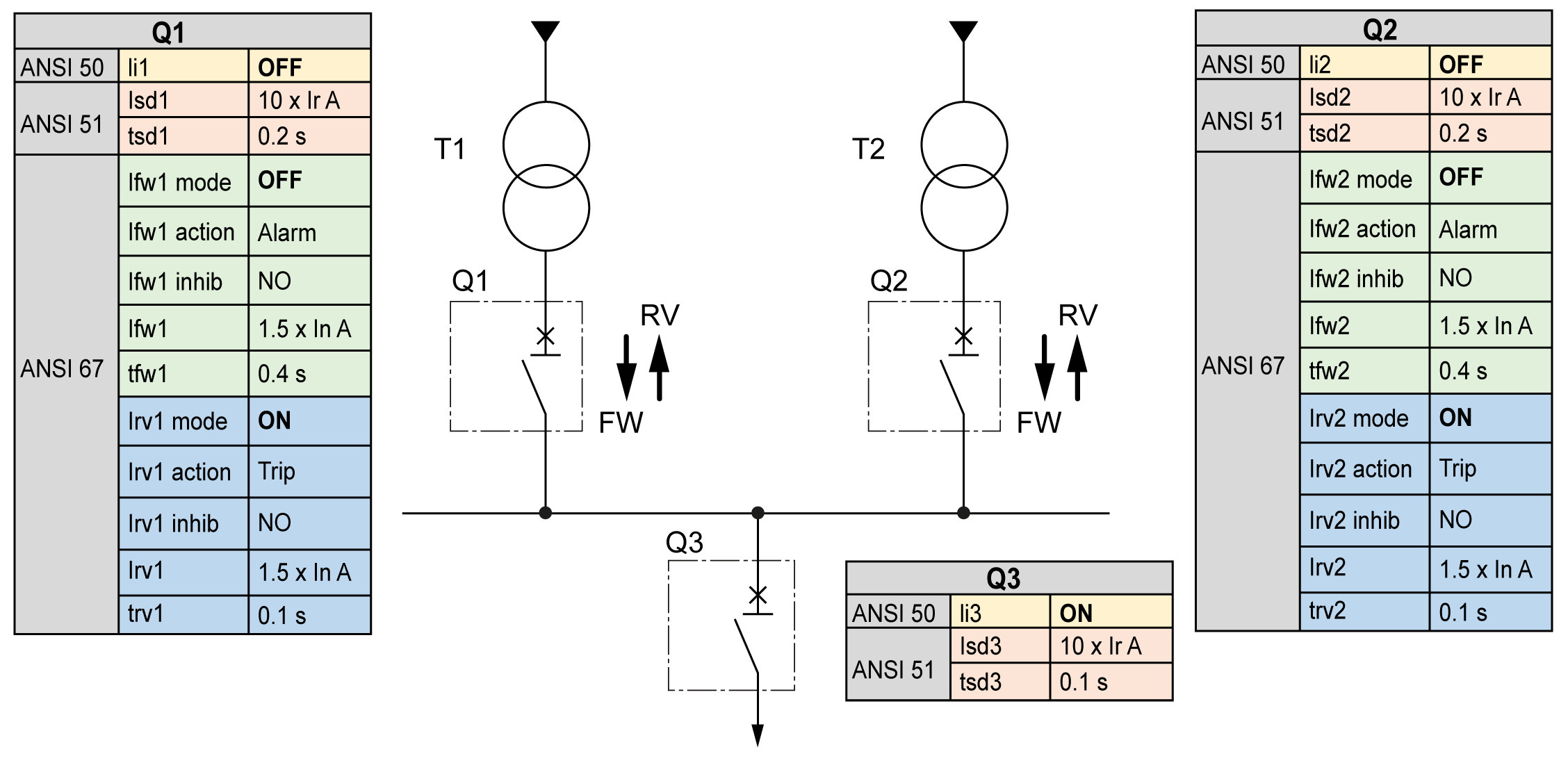
Setting Guidelines for Two Sources with No Tie
The following table indicates the settings of the overcurrent protections of the circuit breakers:
|
Circuit breaker |
ANSI 50 |
ANSI 51 |
ANSI 67 forward |
ANSI 67 reverse |
|---|---|---|---|---|
|
Q1 and Q2 without ANSI 67 |
OFF |
tsd = 0.2 s |
N/A |
N/A |
|
Q1 and Q2 with ANSI 67 |
OFF |
tsd = 0.2 s |
OFF |
trv = 0.1 s |
|
Q3 |
ON |
tsd = 0.1 s |
N/A |
N/A |
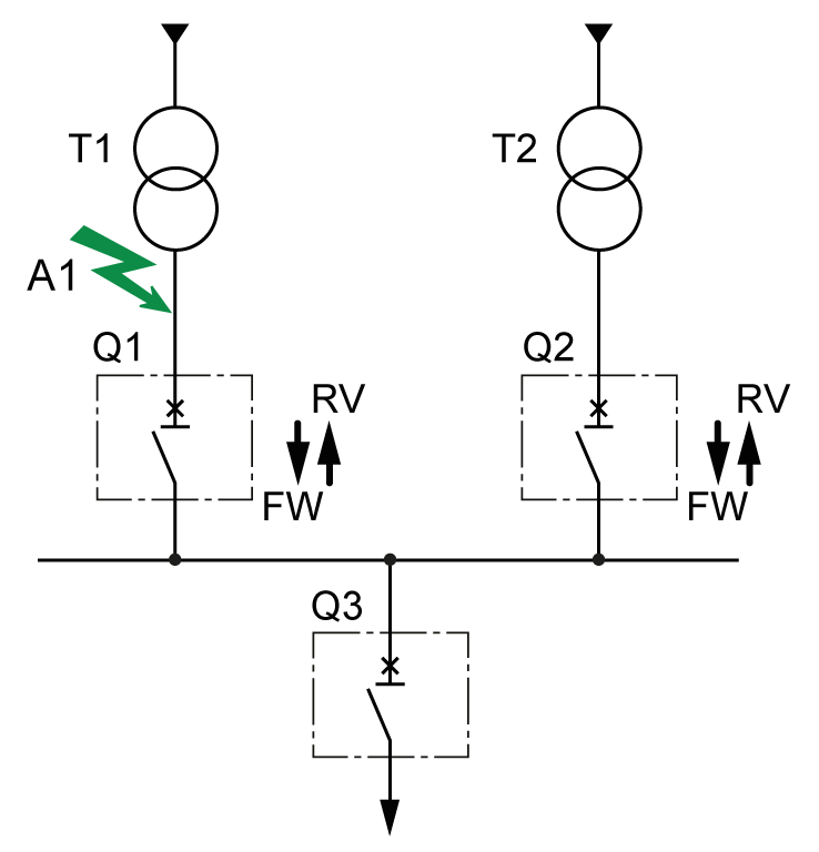
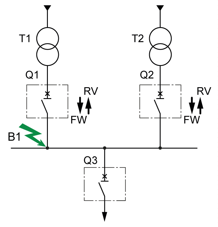
The following table indicates the behavior of the overcurrent protections depending on the location of the short-circuit current:
|
Case |
Q1 and Q2 without ANSI 67 |
Q1 and Q2 with ANSI 67 |
|---|---|---|
|
Short-circuit in A1 |
The busbar is OFF. |
The busbar is ON. |
|
Short-circuit in B1 |
The busbar is OFF. The addition of a tie circuit breaker can keep half of the busbar ON. |
The busbar is OFF. The addition of a tie circuit breaker can keep half of the busbar ON. |
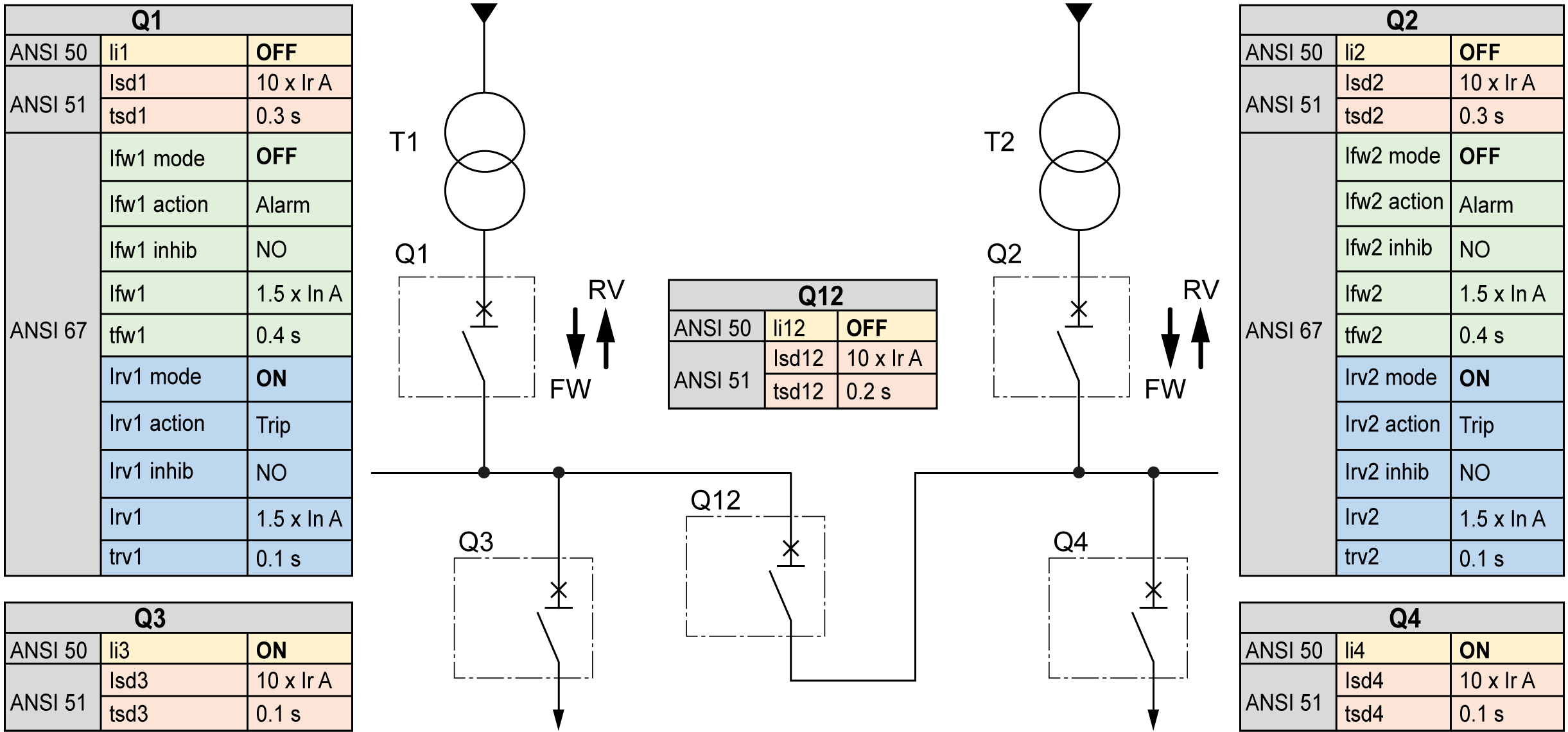
Setting Guidelines for Two Sources with One Tie
The following table indicates the settings of the overcurrent protections of the circuit breakers:
|
Circuit breaker |
ANSI 50 |
ANSI 51 |
ANSI 67 forward |
ANSI 67 reverse |
|---|---|---|---|---|
|
Q1 and Q2 without ANSI 67 |
ON |
tsd = 0.3 s |
N/A |
N/A |
|
Q1 and Q2 with ANSI 67 |
OFF |
tsd = 0.3 s |
OFF |
trv = 0.1 s |
|
Q12 without ANSI 67 |
ON |
tsd = 0.2 s |
N/A |
N/A |
|
Q3, Q4 |
ON |
tsd = 0.1 s |
N/A |
N/A |
The following table indicates the behavior of the overcurrent protections depending on the location of the short-circuit current:
|
Case |
Q1, Q2 without ANSI 67 |
Q1, Q2 with ANSI 67 |
|---|---|---|
|
Short-circuit in A1 |
Half of the busbar (1) is OFF. Half of the busbar (2) is ON. |
The busbar is ON. |
|
Short-circuit in B1 |
Half of the busbar (1) is OFF. Half of the busbar (2) is ON. |
Half of the busbar (1) is OFF. Half of the busbar (2) is ON. |

