
Setting the IDMTL Overcurrent Protection
Setting Guidelines
The IDMTL overcurrent protection Digital Module can be used to improve selectivity with upstream overcurrent protection provided by a fuse or standalone relay, for example, a medium voltage relay, without affecting selectivity with downstream low voltage devices.
Fuses and standalone relays often provide tripping curves which are different from the standard tripping curve offered by MicroLogic X long-time overcurrent protection. The setting guidelines give an indication of how the IDMTL tripping curves can be used to maintain improved selectivity with upstream devices.
Selectivity with Upstream Fuse Using HVF Tripping Curve
The following graph shows how the IDMTL HVF curve can be used to curtail the standard long-time overcurrent protection tripping curve to help improve selectivity with an upstream fuse.
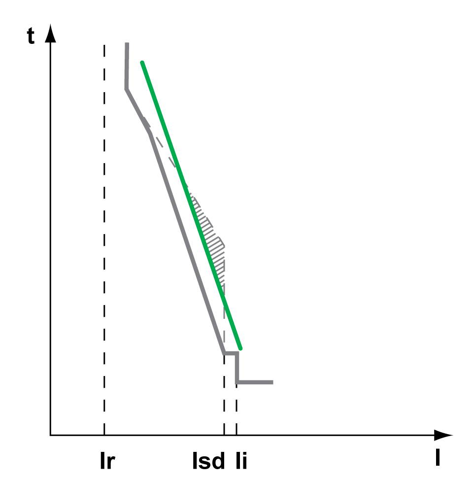
 Upstream fuse tripping curve
 Compromised selectivity
with standard long-time overcurrent protection tripping curve
Compromised selectivity
with standard long-time overcurrent protection tripping curve
 Tripping curve with IDMTL HVF tripping curve
The following settings are recommended for the IDMTL overcurrent protection:
|
Setting |
Value |
|---|---|
|
IDMTL mode |
ON |
|
IDMTL action |
Trip |
|
IDMTL inhibit |
OFF |
|
IDMTL Ir |
1.0 x In(1) |
|
IDMTL tr |
1 s(1) |
|
IDMTL curve |
HVF |
|
IDMTL reset time type |
Definite time |
|
IDMTL reset time |
0 s |
|
(1) The setting proposed is consistent with commonly used high voltage fuses. The setting should be checked on a case-by-case basis. |
|
The following settings are recommended for long-time overcurrent protection:
-
Ir ≤ Iz cable
-
tr = 24 s
Selectivity with Upstream Relay Using DT Tripping Curve
Without IDMTL overcurrent protection, when the MasterPacT MTZ circuit breaker is downstream from a relay using a DT tripping curve, it would be necessary to drastically reduce the long-time overcurrent protection time delay, tr, or the short-time overcurrent protection time delay, tsd, to improve selectivity between the devices. The reduction would significantly reduce the setting options for downstream feeders and in some cases, would make downstream selectivity impossible.
The following graph shows how the IDMTL DT curve can be used to curtail the standard long-time overcurrent protection tripping curve to help improve selectivity with an upstream relay.
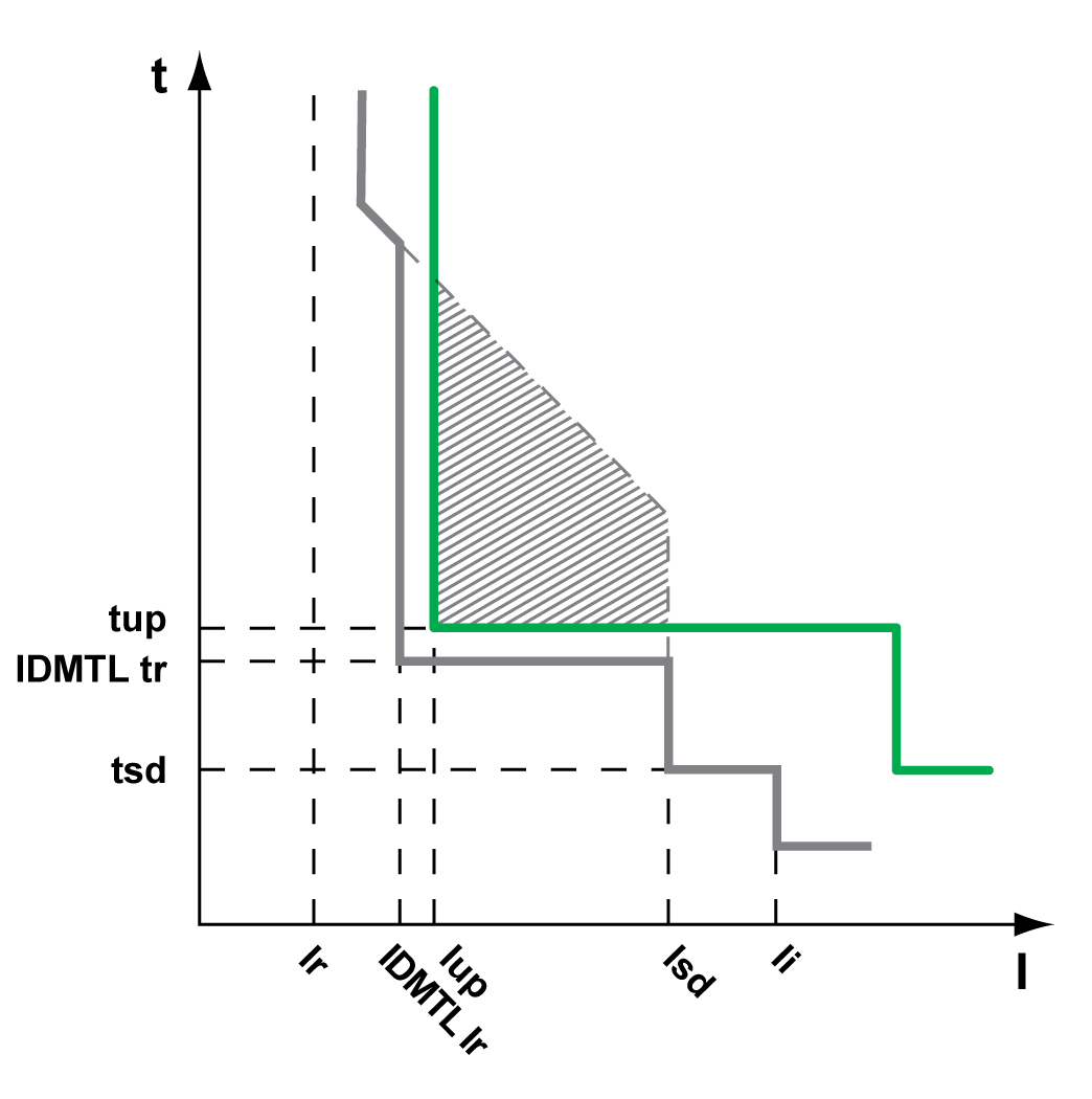
Upstream relay tripping curve
Compromised selectivity
with standard long-time overcurrent protection tripping curve
Tripping curve with IDMTL DT tripping curve
The following settings are recommended for the IDMTL overcurrent protection:
|
Setting |
Value |
|---|---|
|
IDMTL mode |
ON |
|
IDMTL action |
Alarm |
|
IDMTL inhibit |
OFF |
|
IDMTL Ir |
≤1.3 Iup |
|
IDMTL tr |
tsd < IDMTL tr ≤ tup -0.2 s |
|
IDMTL curve |
DT |
|
IDMTL reset time type |
Same as reset type of upstream relay |
|
IDMTL reset time |
Lower than reset time of upstream relay |
Selectivity with Upstream Relay Using SIT or VIT Tripping Curve
As in the previous example, without IDMTL overcurrent protection, when the MasterPacT MTZ circuit breaker is downstream from a relay using an SIT or VIT tripping curve, it would be necessary to drastically reduce the long-time overcurrent protection time delay, tr, or the short-time overcurrent protection time delay, tsd, to improve selectivity between the devices. The reduction would significantly reduce the setting options for downstream feeders and in some cases, would make downstream selectivity impossible.
The following graph shows how the IDMTL SIT or VIT tripping curve can be used to curtail the standard long-time overcurrent protection tripping curve to help improve selectivity with an upstream relay.
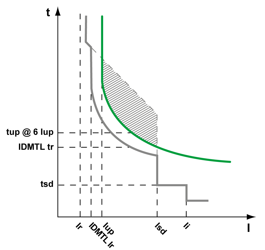
Upstream relay tripping curve
Compromised selectivity
with standard long-time overcurrent protection tripping curve
Tripping curve with IDMTL SIT or VIT tripping curve
The following settings are recommended for the IDMTL overcurrent protection:
|
Setting |
Value |
|---|---|
|
IDMTL mode |
ON |
|
IDMTL action |
Trip |
|
IDMTL inhibit |
OFF |
|
IDMTL Ir |
≤1.3 Iup |
|
IDMTL tr |
tsd < IDMTL tr ≤ tup @ 6 x Iup |
|
IDMTL curve |
SIT or VIT, same as tripping curve of upstream relay |
|
IDMTL reset time type |
Same as reset type of upstream relay |
|
IDMTL reset time |
Lower than reset time of upstream relay |
EIT Tripping Curve Application: Pre-alarm for Load-shedding
An example for the application of this tripping curve is as an adjustable pre-alarm for load shedding.
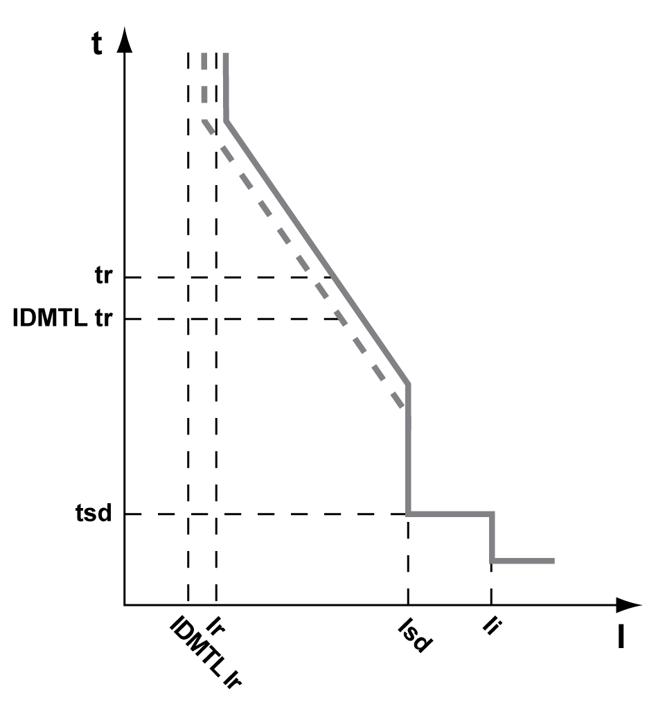
Tripping curve
 IDMTL EIT pre-alarm curve
The following settings are recommended for the IDMTL overcurrent protection:
|
Setting |
Value |
|---|---|
|
IDMTL mode |
ON |
|
IDMTL action |
Alarm |
|
IDMTL inhibit |
OFF |
|
IDMTL Ir |
0.9 Ir |
|
IDMTL tr |
tsd < IDMTL tr ≤ tr |
|
IDMTL curve |
EIT |
|
IDMTL reset time type |
Inverse time |
|
IDMTL reset time |
10 s |