MicroLogic X Control Unit: Description
Introduction
The MicroLogic X control unit includes:
-
LEDs to monitor the status of the circuit breaker
-
A local Human Machine Interface comprising a graphic display with colored backlight, contextual buttons, and dedicated buttons
-
LEDs to monitor the cause of trips and alarms
Control Unit Description
Status LEDs
|
LED |
Description |
|---|---|
|
Ready |
The Ready LED blinks slowly when the standard protection functions of the control unit are operational. |
|
The service LED alerts the user to the health state of the circuit breaker.
|
|
|
ERMS |
The ERMS (Energy Reduction Maintenance Setting) LED has the following statuses:
|
Display Screen with Contextual Buttons and Dedicated Buttons
The local HMI screen and buttons are used to:
-
Navigate the menu structure.
-
Display monitored values.
-
Access and edit configuration settings.
NFC Communication Zone
The NFC communication zone is used to establish an NFC connection between a smartphone running the EcoStruxure Power Device app and the MicroLogic X control unit. When the connection is established, the circuit breaker operating data is automatically uploaded to the smartphone.
Bluetooth Activation Button and LED
The Bluetooth activation button is used to establish a Bluetooth Low Energy connection between a smartphone running the EcoStruxure Power Device app and the MicroLogic X control unit. When the connection is established, the circuit breaker can be monitored and controlled from the smartphone.
When the Bluetooth LED is blinking, it indicates that the MicroLogic X control unit is in communication with a Bluetooth device.
Test Button
The test button is used to test the ground-fault protection for MicroLogic 6.0 X and the earth-leakage protection for MicroLogic 7.0 X.
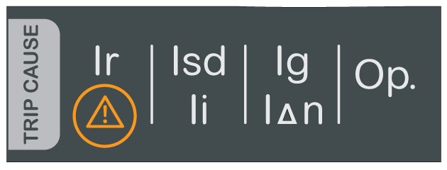
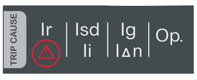
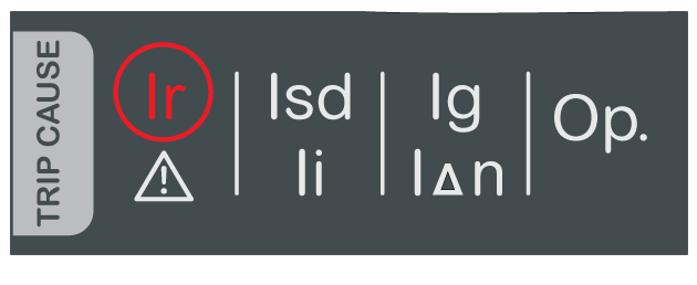
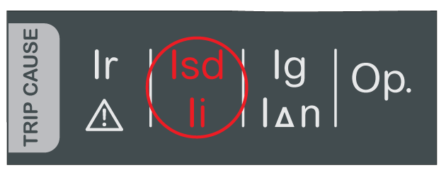
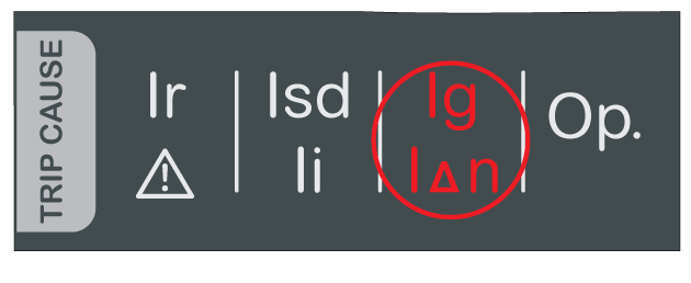
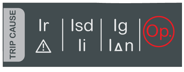
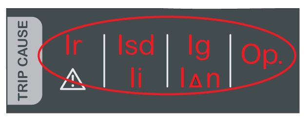
Overload and Trip Cause LEDs
The indications of the four trip cause LEDs depend on the type of MicroLogic X control unit.
Test/Reset Button
The Test/Reset button performs the following functions:
-
Test of the internal battery or check LED functionality: press and hold the Test/Reset button for less than 3 seconds, the four trip cause LEDs switch off for one second. One of the following results:
-
The four trip cause LEDs switch on for two seconds: the battery is OK.
-
The four trip cause LEDs flash sequentially for two seconds: the battery is near the end of its life. Replace the battery.
-
The four trip cause LEDs do not light: replace the battery.
NOTE: This test must be carried out immediately after the replacement of the internal battery to check the correct functioning of the new battery. It can then be carried out at any time in the life of the internal battery. -
-
Reset of the latched events: press and hold the Test/Reset button for more than 3 seconds to reset the latched events. The trip cause LEDs and the service LED switch off.
Mini USB Port
Remove the rubber cover of the mini USB port to connect the following devices:
-
A Mobile Power Pack to supply power to the MicroLogic X control unit.
-
A smartphone running the EcoStruxure Power Device app through USB OTG connection.
QR Code
When the QR code on the front face of a MicroLogic X control unit is scanned with a smartphone running a QR code reader and connected to the Internet, the Go2SE landing page is displayed. The landing page displays some information about the device and a list of menus.
Control Unit Identification Number
The identification number of the MicroLogic X control unit is made up as follows:
-
The serial number of the MicroLogic X control unit in the format PPPPPPYYWWDLNNNN, where the codes are defined as follows:
-
PPPPPP: Plant code
-
YY: Year of manufacture (00 to 99), for example 16 for 2016
-
WW: week of manufacture (01 to 53)
-
D: Day of the week, with 1 representing Monday, for example 5 for Friday
-
L: Unique manufacturing line code or machine code within the plant
-
NNNN: Unique product number (0001 to 9999) generated on the day of manufacture, by the plant manufacturing line or machine
-
-
The commercial reference of the control unit in the format LV8•••••
Use the identification number to register your MicroLogic X control unit through mySchneider app, the customer care mobile application.
Registering your MicroLogic X control unit enables you to keep your records up to date and enables traceability.
Control Unit Type
This code indicates the type of MicroLogic control unit:
-
The number (for example, 6.0) defines the types of protection provided by the control unit.
-
The letter (X) identifies the range of the control unit.
Internal Battery
The internal battery powers the trip cause LEDs and the main diagnostic functions in the absence of any other power supply.
VPS Voltage Power Supply Module
The VPS module provides an internal voltage supply to the MicroLogic X control unit.
The VPS module is optional for MicroLogic 2.0 X, 3.0 X, 5.0 X, and 6.0 X. It is installed as standard on MicroLogic 7.0 X.
Sensor Plug
The protection ranges depend on the rated current In, defined by the sensor plug present below the MicroLogic X control unit.

