
Measures Menu
Presentation
In this guide, electrical phases are described as phase 1, phase 2, phase 3 and cover both IEC standard and UL standard. The MicroLogic X control unit displays the phases as follows:
|
MicroLogic X control unit for IEC standard |
MicroLogic X control unit for UL standard |
|---|---|
|
Phase 1 |
Phase a |
|
Phase 2 |
Phase b |
|
Phase 3 |
Phase c |
Description
The menu contains the following submenus:
|
Level 1 |
Level 2 |
Level 3 |
Function description |
|---|---|---|---|
|
|
|
|
Current real-time measurements |
|
|
Voltage real-time measurements |
||
|
|
Power real-time measurements |
||
|
|
Energy real-time measurements |
||
|
|
Frequency real-time measurements |
||
|
|
Current harmonics real-time measurements |
||
|
|
Voltage harmonics real-time measurements |
||
|
|
Power factor real-time measurements |
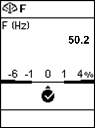
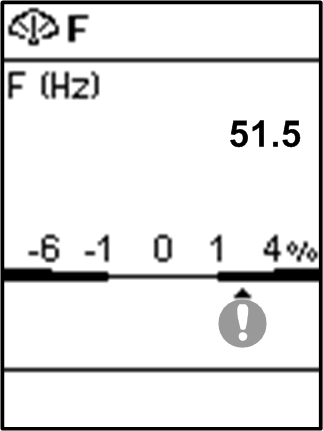
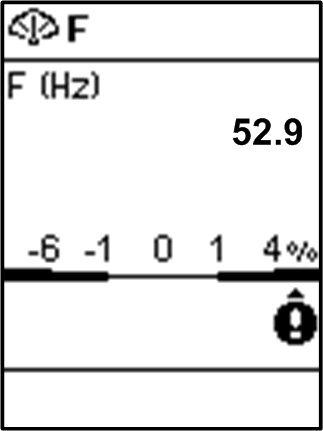
Measures Screens with Quality Gauge
A quality gauge is displayed on the following screens to give a graphical representation of the measurement compared to the expected range:
-
Real-time maximum of 3 phase current unbalances,
-
Average of 3 RMS phase-to-phase voltages
-
Real-time maximum of 3 phase-to-phase voltage unbalances
-
Frequency
For example, for the frequency screen, the following icons indicate the measurement compared to the expected range:
 |
 |
 |
|
|
|
|


Current
The menu presents the following measurements:
|
Level 3 |
Level 4 |
Level 5 |
Parameter name |
|---|---|---|---|
|
|
|
|
RMS current on phase 1 |
|
|
RMS current on phase 2 |
||
|
|
RMS current on phase 3 |
||
|
(1) |
RMS current on neutral |
||
|
(2) |
RMS current on ground |
||
|
(3) |
RMS current on earth leakage |
||
|
|
|
Maximum RMS current on phase 1 |
|
|
|
Maximum RMS current on phase 2 |
||
|
|
Maximum RMS current on phase 3 |
||
|
(1) |
Maximum RMS current on neutral |
||
|
(2) |
Maximum of RMS current on ground |
||
|
(3) |
Maximum of RMS current on earth leakage |
||
|
|
|
Average of 3 phase RMS currents |
|
|
|
|
Real-time maximum of 3 phase current unbalances, with quality gauge |
|
|
|
|
Maximum of maximum of 3 phase current unbalances |
|
|
|
Reset of maximum RMS current, with date and time of last reset |
||
|
(1) Applies to 4-pole circuit breakers or 3-pole circuit breakers with ENCT wired and configured (2) Applies to MicroLogic 2.0 X, 3.0 X, 5.0 X, 6.0 X (3) Applies to MicroLogic 7.0 X |
|||
Voltage
The menu presents the following measurements:
|
Level 3 |
Level 4 |
Level 5 |
Parameter name |
|---|---|---|---|
|
|
|
|
RMS phase-to-phase voltage 1-2 |
|
|
RMS phase-to-phase voltage 2-3 |
||
|
|
RMS phase-to-phase voltage 3-1 |
||
|
(1) |
RMS phase-to-neutral voltage 1-N |
||
|
(1) |
RMS phase-to-neutral voltage 2-N |
||
|
(1) |
RMS phase-to-neutral voltage 3-N |
||
|
|
|
Maximum RMS phase-to-phase voltage 1-2 |
|
|
|
Maximum RMS phase-to-phase voltage 2-3 |
||
|
|
Maximum RMS phase-to-phase voltage 3-1 |
||
|
(1) |
Maximum RMS phase-to-neutral voltage 1-N |
||
|
(1) |
Maximum RMS phase-to-neutral voltage 2-N |
||
|
(1) |
Maximum RMS phase-to-neutral voltage 3-N |
||
|
|
|
Minimum RMS phase-to-phase voltage 1-2 |
|
|
|
Minimum RMS phase-to-phase voltage 2-3 |
||
|
|
Minimum RMS phase-to-phase voltage 3-1 |
||
|
(1) |
Minimum RMS phase-to-neutral voltage 1-N |
||
|
(1) |
Minimum RMS phase-to-neutral voltage 2-N |
||
|
(1) |
Minimum RMS phase-to-neutral voltage 3-N |
||
|
|
|
Average of 3 RMS phase-to-phase voltages (V12+V23+V31)/3, with quality gauge |
|
|
(1) |
Average of 3 RMS phase-to-neutral voltages (V1N+V2N+V3N)/3 |
||
|
|
|
Real-time maximum of 3 phase-to-phase voltage unbalances, with quality gauge |
|
|
(1) |
Real-time maximum of 3 phase-to-neutral voltage unbalances |
||
|
|
|
Maximum of maximum of 3 phase-to-phase voltage unbalances |
|
|
(1) |
Maximum of maximum of 3 phase-to-neutral voltage unbalances |
||
|
|
Reset of minimum and maximum RMS voltage, with date and time of last reset |
||
|
(1) Applies to 4-pole circuit breakers or 3-pole circuit breakers with ENVT wired and configured. |
|||
Power
The menu presents the following measurements:
|
Level 3 |
Level 4 |
Level 5 |
Parameter name |
|---|---|---|---|
|
|
|
|
Active power on phase 1 |
|
|
Active power on phase 2 |
||
|
|
Active power on phase 3 |
||
|
|
Total active power |
||
|
|
|
Maximum total active power |
|
|
|
(1) |
Reactive power on phase 1 |
|
|
(1) |
Reactive power on phase 2 |
||
|
(1) |
Reactive power on phase 3 |
||
|
|
Total reactive power |
||
|
|
|
Maximum total reactive power |
|
|
|
(1) |
Apparent power on phase 1 |
|
|
(1) |
Apparent power on phase 2 |
||
|
(1) |
Apparent power on phase 3 |
||
|
|
Total apparent power |
||
|
|
|
Maximum total apparent power |
|
|
|
Reset of maximum power, with date and time of last reset |
||
|
(1) Applies to 4-pole circuit breakers or 3-pole circuit breakers with ENVT wired and configured. |
|||
Energy
The menu presents the following measurements:
|
Level 3 |
Level 4 |
Level 5 |
Parameter name |
|---|---|---|---|
|
|
|
|
Total active energy |
|
|
Total reactive energy |
||
|
|
Total apparent energy |
||
|
|
|
Total active energy delivered into the load (counted positively) |
|
|
|
Total reactive energy delivered into the load (counted positively) |
||
|
|
|
Total active energy received out of the load (counted negatively) |
|
|
|
Total reactive energy received out of the load (counted negatively) |
||
|
|
Reset of accumulated energy, with date and time of last reset |
||
Frequency
The menu presents the following measurements:
|
Level 3 |
Level 4 |
Level 5 |
Parameter name |
|---|---|---|---|
|
|
|
|
Frequency with quality gauge |
|
|
|
Maximum frequency |
|
|
|
|
Minimum frequency |
|
|
|
Reset of minimum and maximum frequency, with date and time of last reset |
||
I Harmonics
The menu presents the following measurements:
|
Level 3 |
Level 4 |
Level 5 |
Parameter name |
|---|---|---|---|
|
|
|
|
Total Harmonic Distortion (THD) of current on phase 1 compared to the fundamental |
|
|
Total Harmonic Distortion (THD) of current on phase 2 compared to the fundamental |
||
|
|
Total Harmonic Distortion (THD) of current on phase 3 compared to the fundamental |
||
|
(1) |
Total Harmonic Distortion (THD) of current on neutral compared to the fundamental |
||
|
(1) |
|
Maximum of Total Harmonic Distortion (THD) of current on neutral compared to the fundamental |
|
|
|
) |
Average of 3 phase current Total Harmonic Distortions (THD) compared to the fundamental |
|
|
|
) |
Maximum average of 3 phase current Total Harmonic Distortions (THD) compared to the fundamental, with date and time of occurrence |
|
|
|
Reset of minimum and maximum THD, with date and time of last reset |
||
|
(1) Applies to 4-pole circuit breakers or 3-pole circuit breakers with ENVT wired and configured. |
|||
V Harmonics
The menu presents the following measurements:
|
Level 3 |
Level 4 |
Level 5 |
Parameter name |
|---|---|---|---|
|
|
|
|
Total harmonic distortion (THD) of phase-to-phase voltage 1-2 compared to the fundamental |
|
|
Total harmonic distortion (THD) of phase-to-phase voltage 2-3 compared to the fundamental |
||
|
|
Total harmonic distortion (THD) of phase-to-phase voltage 3-1 compared to the fundamental |
||
|
(1) |
Total harmonic distortion (THD) phase-to-neutral voltage 1-N compared to the fundamental |
||
|
(1) |
Total harmonic distortion (THD) phase-to-neutral voltage 2-N compared to the fundamental |
||
|
(1) |
Total harmonic distortion (THD) phase-to-neutral voltage 3-N compared to the fundamental |
||
|
|
|
Average of 3 phase-to-phase voltage Total Harmonic Distortions (THD) compared to the fundamental |
|
|
(1) |
Average of 3 phase-to-neutral voltage Total Harmonic Distortions (THD) compared to the fundamental |
||
|
|
|
Maximum value since last reset of average of 3 phase-to-phase voltage Total Harmonic Distortions (THD) compared to the fundamental |
|
|
(1) |
Maximum value since last reset of average of 3 phase-to-neutral voltage Total Harmonic Distortions (THD) compared to the fundamental |
||
|
|
Reset all maximum and minimum voltages |
||
|
(1) Applies to 4-pole circuit breakers or 3-pole circuit breakers with ENVT wired and configured. |
|||
Power Factor Menu
The menu presents the following data:
|
Level 3 |
Level 4 |
Parameter name |
|---|---|---|
|
|
|
Total power factor |
|
|
Total fundamental power factor |
|
|
|
The parameters displayed depend on the sign convention for power factor and cos phi selected.
|