
GIS Attributes for Generic or Shared Components
To understand the extra steps while configuring GIS Attributes for generic or shared components, it requires a bit of context.
Context
To improve performance, Designer XI combines some GIS feature classes into the same component type. For example, the application takes primary overheads, primary underground, secondary overheads, and secondary undergrounds and combines them into the conductor component. Upon push, the application breaks them apart again so that they are imported into the proper feature class in the GIS.
To improve performance and accommodate a variety of feature classes that do not have a specific toolset, the application combines other feature classes into “generic” or “shared “component types. For example, these include the Electric Network Component and the Gas Generic Point Component.
These generic “buckets” can contain many different feature classes. And, these different feature classes might have the same field names. For example, they all might have a Manufacturer Name field. Further, all their Manufacturer Name fields might be configured with different coded value domains. You might have different manufacturers for sectionalizers than you do for street lights. When you configure the Manufacturer Name as a GIS Attribute field, the application unions all the coded value domains together. This produces a long list of values, many of which do not apply to the feature in the design (in other words, the manufacturers for sectionalizers would appear in the same list as the manufacturers for street lights).
In short, there are extra steps when configuring GIS Attributes for generic or shared components in order to specify which component in the group is mapped to which coded domain.
Procedure
The steps below apply for the following components types:
-
Electric Network Component Bank
-
Electric Network Component Unit
-
Gas Generic Point Component
-
Surface Structures
To configure GIS Attributes for generic or shared components, follow these steps:
-
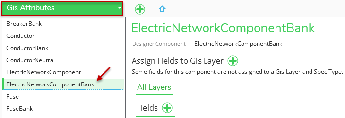
In the Catalog tab > Electric or Gas Schema, use the drop-down to choose GIS Attributes.
-
Click the shared component. The following image uses ElectricNetworkComponentBank.
-
First, let’s start by mapping a field across all members of the shared component. To do so:
-
Click All Layers, if necessary. Then, click the Add Field
 button next to Fields.
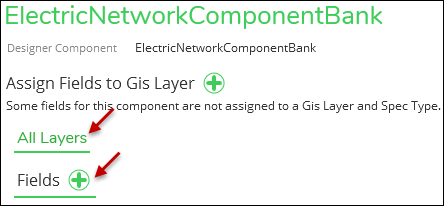
-
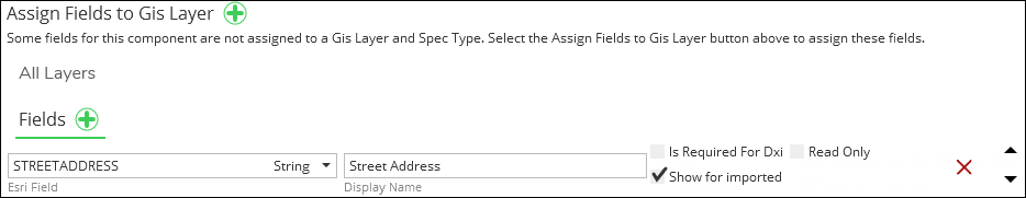
A new row appears. Use the drop-down to choose the appropriate field. In this example, we are using the Street Address field.
-
Type a user-friendly Display Name. If left empty, it defaults to the field alias.
-
Check the box next to “Is Required for DXI” to mark the field as required. The field displays in red in the Designer XI application. Leave the box unchecked to keep the field as optional.
-
Check the box next to “Show for Imported” to also include this attribute for imported components that are not part of the design. The user cannot edit attributes for imported components, but including the attribute in read-only format could be helpful for designers.
IMPORTANT:-
Attributes are typically for new components (those added, replaced, or modified as a part of the design). This “Show for Imported” check box is the one exception. This check box determines if you also want to see this attribute for existing components.
-
In order to see the field and its attributes in the application, the field must actually have data in it. A null field in the GIS does not appear. For example, in the image below, the administrator is choosing to show Foundation Type for existing poles. If the end user in the application selects a pole that has a null value for Foundation Type, then both the field name and the null attribute do not appear in the Component Information pane for that particular pole.
-
-
Check the box “Read Only” to allow users to see the field for imported components, but not to edit the field for new components. If you check “Read Only,” the field does not appear in the attribute editor within Designer XI.
 TIP: The “Read Only” check box really only makes sense if the “Show for Imported” check box is also checked. If you checked “Read Only” by itself, you are stating you do not want designers to see that field for new components, and since “Show for Imported” isn’t checked, that field wouldn’t be visible for existing features either. In short, the field would be completely hidden, and in that case, you wouldn’t map it at all. By checking both, you are stating that you want users to see the field for existing features, but not be able to edit that same field for new components.
 -
Click Save. At this point, the Street Address is now mapped for all members of the shared components.
IMPORTANT: Make sure the field actually exists for all members of the shared component. By including the field under All Layers, the field displays in the attribute editor in Designer XI even if that field doesn’t exist for that particular component. -
Continue as necessary. If adding multiple fields, use the up and down arrows on the far, right-hand side of the interface to configure the Sort Order.
-
-
Now, let’s map a field for a specific member of the shared component. In this example, we use Street Light as our specific component. To do so:
-
Click the Add Field
button next to Assign Fields to GIS Layer.
-
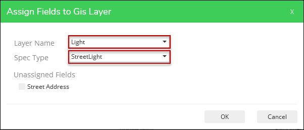
Choose the appropriate Layer Name. The Layer Name determines the fields that are available to add. You see these fields after you close this dialog.
-
Choose the Spec Type. This drop-down includes all the spec types that exist in the shared component (in this example, all the spec types that exist in the Electric Network Component Bank).
-
The fields you added to all members of the shared component (step 3 above) appear under Unassigned Fields. In the previous example, we added Street Address to all members of the shared component.
-
If you want to keep the Unassigned Fields on all of the shared components, do not check the boxes by the field names. By leaving them unchecked, you are leaving them assigned to all members of the shared component.
-
If you want to transfer Unassigned Fields to the component you are currently working on (in this case, Street Light), then check the boxes next to the fields you want to transfer. They are removed from all members of the shared component and added only to the component you are working on currently.
-
-
Click OK.
-
Now, you have a new tab to the right of All Layers. In this example, it is Light.StreetLight.

-
Click the Add Field
button next to Fields. -
Add fields as described in Step 3 above.
-
Click Save when finished.
-
When adding attributes, keep the following in mind:
-
To see your GIS Attributes in the Designer XI application, you need to restart the Edge Service if you are using an on-premises version of the service. The Hosted Edge Service will pick up configuration changes as they occur.
-
However, there is no Catalog Cache. Thus, you do not need to Update Cache.
-
-
If you want to verify the fields in the Designer XI application:
-
For new install components, you can open a different design to verify the new fields.
-
But, to verify “Show for Imported,” you need to initialize a new design after restarting the Edge Service to see the new fields.
-
- For “Show for Imported,” in order to see the field and its attributes in the application, the field must actually have data in it. A null field in the GIS does not appear.
Sort Order within Shared Components
In the steps above, there are fields assigned to All Layers and there are fields assigned to specific members of the shared component. Both of these lists of fields have a Sort Order.
The application merges the Sort Orders when displaying the list of fields to the end user in the application. Thus, keep both the All Layers fields’ orders and the specific layer fields’ orders in mind while determining Sort Order. For example, do not duplicate Sort Order numbers.