General
On the General subtab, you set high-level configurations and labels. You also choose the Work Location assignment configuration for linear components. The configurations on the General subtab include the following:
-
Address Locator Search Locale: Your country.
-
FacilityID Generator Service URL: The published service for the Facility ID Generator (as users place new components in a design, those components are automatically assigned a Facility ID). This is an optional configuration.
-
Design Storage Service URL: The URL for the Design Storage Service.
IMPORTANT:-
The URL must be secured using HTTPS. An un-secured HTTP URL is not accepted in this field.
-
High Availability Considerations: The Design Storage service is a web site running under IIS. To support high availability, this web service must be installed on two (or more) web servers, and a load balancer must be introduced to redirect requests among these servers. Because the servers are in a high-availability pair, you should deploy a load balancing URL in order for requests made to the Design Storage service to hit both endpoints. Then, paste the load balancing URL in this field.
-
-
AGS Polyfill Service URL: The URL of the ArcGIS Server Polyfill Service (this field requires a feature flag).
IMPORTANT: The URL must be secured using HTTPS. An un-secured HTTP URL is not accepted in this field. -
Assignment Due Date Label: The label for the Assignment Due Date.
-
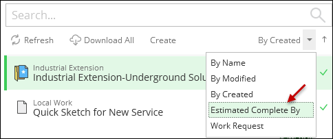
This label becomes the 4th sort option. Users can sort ascending or descending by this date field.
-
If you leave the field empty, the application defaults to using “Due Date” as the label.
-
-
Assign Linear CU To: Work Locations act as logical grouping points for CUs within a design. Work Location use geographic proximity to “collect” the CUs into a group. Point components belong to the closest Work Location. But, what about linear components such as conductors or pipes? They could span near multiple Work Locations. This configuration chooses where those linear components group by default.
-
Start Work Location: All linear components have a start point. This is the point at which the sketch started. The application uses that start point to determine which Work Location is closest to the linear feature.
-
Start-to-End Work Locations (span): This creates a “Span Work Location” for linear components. For example, if the start of the linear component is near Work Location 1, and the end of the component is near Work Location 2, the component belongs to “Work Location 1–2.”
-
-
Allow Designs to be Copied: This allows the user to make a copy of an existing design in the application. See Add New Design or Copy Existing Design for more information.
-
Allow Multiple FacilityID Requests: This allows the user to click the Update Facility IDs tool multiple times. This tool works with your FacilityID Generator Service URL.
-
Measure Tool Precision: This determines how many decimals are displayed when using the Measure Tool.
-
kV Decimal Precision: Operating voltage is visible on the Component Information pane for all electric components, which is useful for symbology and labeling purposes. The kV Decimal Precision determines how many decimals to display for the operating voltage.
-
Enable Additional Equipment: Previously, Load Break Switch, Capacitor, Sectionalizer, Voltage Regulator, Fault Indicator, and Distributed Generator did not have a specific Designer XI component. If you wanted to model these electric devices, they were configured as electric network components (ENCs). Now, these electric devices have specific, Designer XI components. So, if you had previously modeled these as ENCs, but now they have components, what should you do?
-
If you have previously modeled an electric asset as an electric network component and now that asset has a specific component, that is OK. Designer XI supports such assets, for example a capacitor, whether it is modeled as a capacitor or an electric network component.
-
You can keep them as electric network components (again, for example, you can keep capacitors as electric network components). The benefit is that there are no configuration changes needed. However, your end users might naturally want to sketch the Designer XI capacitor component, but they won’t find capacitors there. Instead, they find them as electric network components. This could be confusing.
-
You can migrate your electric network components into their specific Designer XI components. This requires configuration effort to transition the component types. The benefit is your end users can sketch the specific Designer XI component types instead of using the generic electric network components.
Thus, while you are deciding on your configuration path, you can choose to either show or hide these components in the Designer XI application using this toggle.
-
-
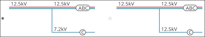
Display Voltage: This determines how the Designer XI client application should treat operating voltage when a line is split. The first option displays a calculated “line-to-ground” voltage on the split line. With the second option, the split conductor inherits the upstream “line-to-line” voltage.