
Table Mapping for Complex Edges
In the GIS, a complex edge is a line feature that is not split at each junction. Complex edges are commonly used for electric primary conductors and gas distribution mains. In this manner, the primary conductor or main gets to maintain a single shape even though numerous pieces of equipment are snapped into it. In short, it makes it easier to maintain the shape of the primary or main while working in the map.
However, in Designer XI, you are able to select individual parts of the complex edge (for example, you might need to replace only a segment of the primary in the field). So, what does this mean for the complex edge record in the GIS when only a part is edited? The answer is the other sections are re-created when the design is pushed back to the GIS.
To preserve existing attributes for the re-created sections, this topic recommends table mapping in the schema any field you want to preserve. In short, the field attributes are brought into Designer XI upon Import, and are brought back to the GIS upon Push.
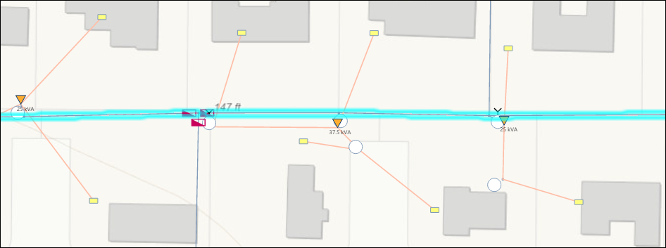
For example, this primary is stored as a complex edge in the GIS (in other words, it is a single shape in the GIS):
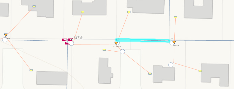
But in Designer XI, you can select a single segment of the complex edge:
So, if the user replaces just this one segment in the application, the other sections are re-created and added back into the GIS.
Because you do not want to lose any attributes, you should map any field that you want re-populated with the same data that was in the GIS. Further, set those fields to both Import and Push to GIS. In that manner, all attributes are present in Designer XI, and thus they are added back along with the other sections of the complex edge in the GIS.