
Work Areas
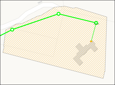
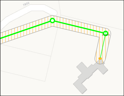
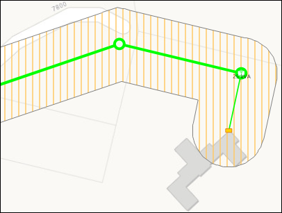
Work Areas are the “footprint” or boundary of the design. They are particularly helpful to give designs a defined space, and to inform other designers of activity in the area. The symbology (fill, style, and outline) are configurable at the company level, and the following image is just an example.
Prerequisite: The Work Area Must be in the Published Map Service
Before you can configure the Work Area in the Work Areas tab, the feature class itself must be included in the published map service. This is the map service found on either the Electric or Gas subtab.

-
If your company is utilizing the GIS Push Feature Service, then the Work Areas subtab consumes this published service.
-
If your company is not utilizing the GIS Push Feature Service, then the Work Areas subtab consumes the Network Feature Service.
When creating the Work Area feature class, follow these guidelines:
-
It must be a polygon.
-
It must be included in the published map service that satisfies the Network Feature Service. Do not worry about its symbology in the feature service, as you set the symbology in the Work Areas subtab.
-
Because it is included in the Network Feature Service and because the other feature classes in that service are registered as versioned, the Work Area feature class must also be registered as versioned.
-
It must have the Required fields below.
-
You can change the field names below. However, later you map these fields in Solution Center, and if you name them as displayed in the table, it is easier to know which fields should be mapped together because the names are the same. Finally, you can increase the field lengths if your company attributes require more characters.
Required/ Recommended
Field Name
Field Type and Length
Description
Required
DesignID
GUID
Stores the Design ID created by the application
Required
WorkOrderID
Text, 50
Stores the Work Order ID generated by the integrated WMS
Required
Designer
Text, 50
Stores the name of the designer assigned to the job
Required
JobStatus
Text, 50
Stores the progress status of the design
Required
ObjectID
Object ID
Required field for all Esri feature classes
Required
GlobalID
Global ID
Auto-generated ID
Recommended
WorkflowStatus
Short Integer
Reserved for future use to track status independent of Job Status
Recommended
Description
Text, 255
Reserved for future use to provide a text field for designer notes
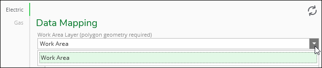
Map the Work Area to the Published Map Service
After successfully publishing the map service to include the Work Area feature class, you are ready to configure the Work Area in the application.
-
In Mapping > Work Areas, click either Electric or Gas.
-
Click Create.
-
For Work Area Layer, use the drop-down to choose the Work Area polygon feature class included in the published map service. The name might differ from the image below, as it depends on what you named it in the service.
-
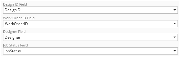
Map the remaining fields to the appropriate fields in the Work Area feature class. The Names might vary from the image below depending on how you named the fields when you created the feature class.
-
Click Save.
Choose Work Area Symbology
After mapping the Work Area fields, set the symbology of how the Work Area should look and feel in the map. You can have one symbology for electric and another for gas. When configuring the symbology, the best way to see how it is going to look is to set it in Solution Center, then open a design in Designer XI. When you re-open a design, the Work Area takes on the new symbology.
-
Type a buffer width.
-
As an example, a buffer width of 5 meters looks like this:
-
And, a buffer width of 15 meters looks like this:
-
-
Choose a Fill Style and Fill Color. The best way to view the symbology is in the Designer XI application, but here are examples of the Fill Style to get you going:
Fill Style
Symbology
Backward Diagonal

Cross

Diagonal Cross

Forward Diagonal

Horizontal

(None)

Solid

Vertical

-
Choose an Outline Style, Outline Color, and Outline Width.
-
Click Save.
-
View a design in Designer XI to confirm the Work Area symbology.
Publish Operational Map for Work Areas
It is strongly recommended to include the Work Area polygon feature class either as its own stand alone Operational Map or as a part of a larger Reference Map. In the latter situation, you then create a Reference View from the Operational Map that only includes the Work Area. This is important, because this allows designers to turn on the Work Areas in the Designer XI application in order to see what other work is happening in proximity to their design. Designers can, by default, see the Work Area for their current design, but it is through either a Reference Map or View that designers see other Work Areas.