
Macro CU
This tab shows the compositions of existing Macro CUs. You can also add new Macro CUs or edit existing Macro CUs.
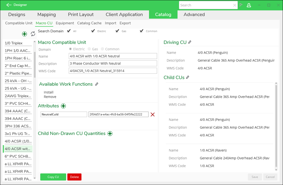
You can perform the following actions:
-
Click the Add
 button to add a new Macro CU, add Macro CU Attributes, or add
default quantities for non-drawn CUs.
button to add a new Macro CU, add Macro CU Attributes, or add
default quantities for non-drawn CUs. -
Click the Edit
 button to either edit the Driving CU, Child CUs, or change
the Available Work Functions.
button to either edit the Driving CU, Child CUs, or change
the Available Work Functions. -
Click Copy CU as a first step toward modifying and creating a new CU.
-
Click Delete to delete a Macro CU.
Example Workflow to Create a Macro CU for a Three-Phase Conductor with a Neutral
A multiple-phase conductor is a great example of a Macro CU. The steps below assume your CUs are configured and ready to be assembled together to create the Macro CU. Further, these steps are for creating a single Macro CU, but know that you can import multiple Macro CUs simultaneously using the Import subtab. See the topics Compatible Units and Import/Export for more information about configuring the underlying CUs and importing CUs in bulk.
-
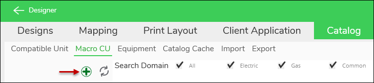
If necessary, navigate to Catalog > Macro CU.
-
Directly above the list of current Macro CUs, click Add.
-
Populate the fields under Macro Compatible Unit.
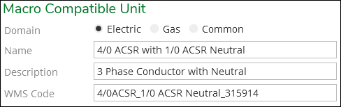
These fields are visible to the end-user in the Designer XI application. For example, here is what the same Macro CU looks like from the end-user’s point of view:

-
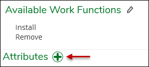
Choose Available Work Functions.
-
By Available Work Functions, click Edit.

-
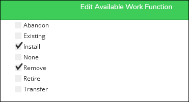
Click Edit Available Work Function.

-
Check the appropriate Work Functions, then click Apply.
-
-
Choose the Driving CU. This CU is sketched on the map, and other CUs that represent the other phases and neutral are added as Child CUs.
-
By the Driving CU, click Edit.

-
Type either part of the Name, Description, or WMS Code for the CU you need, then click Search. This winnows the list of available CUs to only those matching your search.
 IMPORTANT: Designer XI supports single, two, and three phase components. The number of phases automatically informs the snapping behavior to ensure snapped components have like-minded phasing (for example, you cannot snap a three-phase fuse to a single-phase conductor). When configuring the CU catalog, a CU can have a related equipment specification comprising one phase or multiple phases. In other words, if you are building a three-phase Macro CU, the Driving CU could be related to a specification that carries all three phases. Or, the Macro CU can comprise three CUs all related to a single-phase specification. The choice really depends on what your final system of record requires, as the GIS consumes the records differently upon upload (multiple CUs related to single-phase specifications results in more records, for example).
 -
Select your CU, and notice it displays information about the CU including its Work Functions, Related Equipment, and other Macro CUs that it already participates in.
-
Click Add to accept the CU as your Driving CU. This returns you to the main page. You are allowed one CU to act as the Driving CU.
-
-
Choose the Child CUs. These CUs are not sketched on the map. They represent the other phases and the neutral for this three-phase conductor. The steps to add Child CUs are similar to adding the Driving CU:
-
By the Child CUs, click Edit.
-
Type either part of the Name, Description, or WMS Code for the CU you need, then click Search. This winnows the list of available CUs to only those matching your search.
-
Select your CU, and notice it displays information about the CU including its Work Functions, Related Equipment, and other Macro CUs that it already participates in.
-
Click Add to accept the CU as a Child CU.
-
Continue to add Child CUs. As you add them, they appear as a list under the Current heading.

-
When you have all the Child CUs you need, click Done.
-
-
In this three-phase conductor example, the neutral’s GUID is added as a Macro CU Attribute. In this manner, the cost of the neutral is captured appropriately without affecting snapping rules in the application. In other words, without separating out the neutral in this manner, it would be treated as a phase in the application, which is not correct.
-
Look up the GUID for the cable CU representing the neutral. Most likely, it is easiest to run an Export from the Export subtab and find it in the list of CUs. See the topic Import/Export for more information about exporting.
-
Once you have located the GUID for the cable CU, copy it.
-
Return to the Macro CU you are building in Solution Center.
-
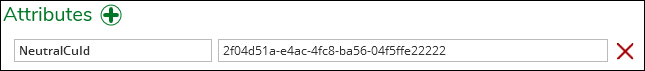
By Attributes, click Add.
-
Type the name of the Macro CU Attribute field. This name must match the Esri field name as stored in the Schema.xml.
-
Paste the GUID you copied earlier for the cable CU.
-
In the lower, right-hand corner of the application, click Save.
-
-
If needed, add non-drawn CUs and their quantities. The three-phase conductor does not have an example for this, but pole Macro CUs commonly have assemblies, hardware, and other support components added as non-drawn CUs.

-
In order to test your new Macro CU in the application, there is one more step: update the CU Cache prior to testing. If you are building a few Macro CUs and want to test them all when you are finished, you can wait to update the CU Cache after you build your last Macro CU. To update the cache:
-
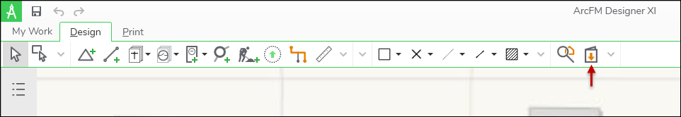
Click the Catalog Cache subtab.
-
Near Macro Compatible Units, click Update Cache.

-
After the update completes, update your CU Catalog in Designer XI and test your new Macro CU. Updating within the application is only necessary if Designer XI was already open while you were building the Macro CU (Designer XI always checks the cache every time it is launched).
-