Status Monitoring and Load Control
PowerTag Control IO 230 V Module
Load control with feedback loop can be achieved with PowerTag control IO 230 V module (reference A9XMC1D3).
 WARNING WARNING |
|---|
|
UNEXPECTED START OF OPERATION
Only use PowerTag control IO 230 V module (reference A9XMC1D3) and PowerTag control 2DI 230 V module (reference A9XMC2D3) to control electrical
loads that can be safely left unattended.
Failure to follow these instructions can result in death, serious injury, or equipment
damage.
|
With this solution, it is possible to easily control remotely a contactor (CT) or an impulse relay (TL) with or without the information of the load circuit contact using the associated input.
Local Output Control
During the commissioning phase, you will select whether the output order should be a pulse (for impulse relay) or a latch order (for contactor). Once the IO module has been commissioned, the front face push button allows to change the status of output control circuit.
Commissioning and decommissioning are done through webpages.
The push button can also be used for decommissioning in case of communication loss (>240 s)
To commission or decommission the PowerTag control IO 230 V module, refer to Wireless Device Commissioning with Webpages or refer to EcoStruxure Power Commission Online Help.
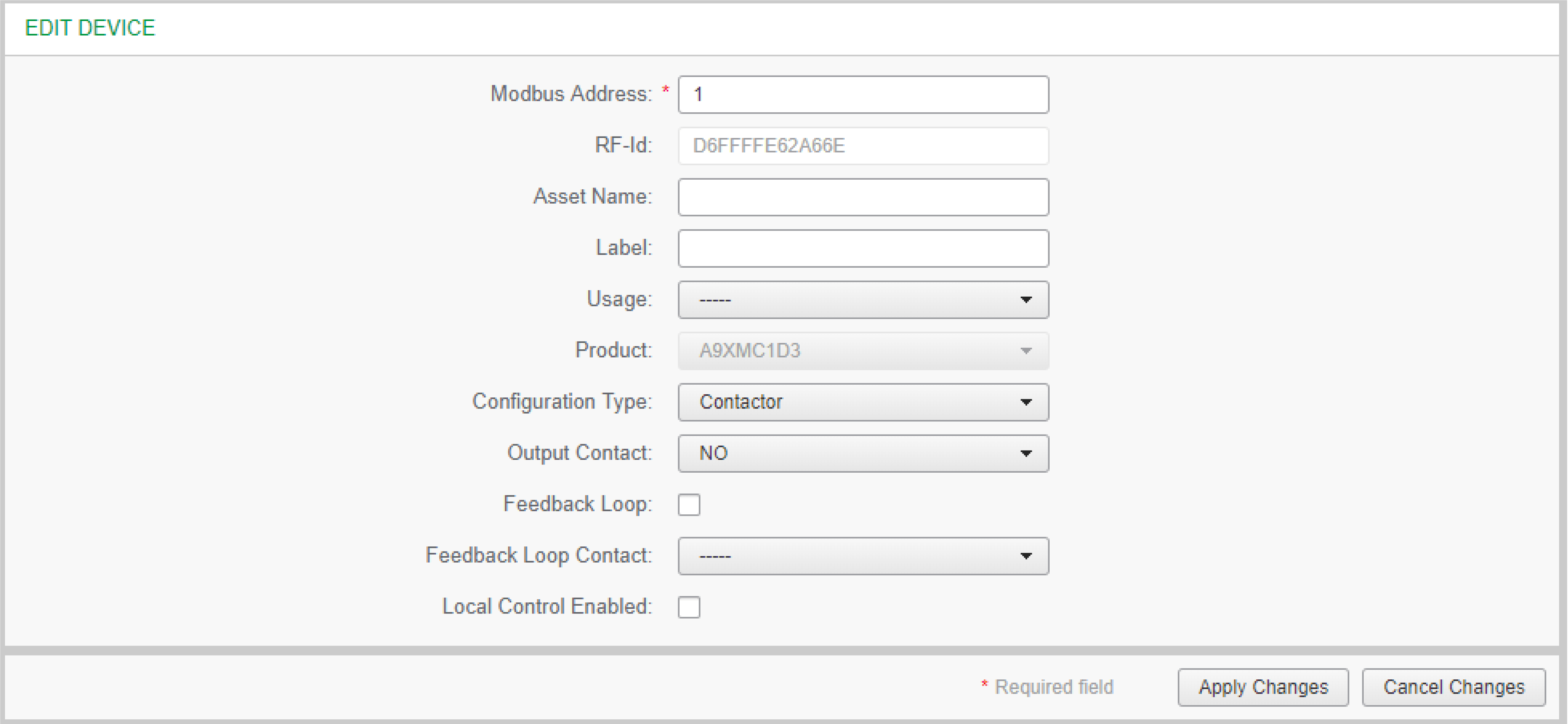
To configure the PowerTag control IO 230 V module, refer to the following procedure or EcoStruxure Power Commission Online Help.
|
Step |
Action |
|---|---|
|
1 |
Click Start Scanning to discover the wireless devices connected to the PowerTag Link gateway. Result: Displays the discovered wireless devices and assigns Modbus address to each device. |
|
2 |
Select any wireless device and click the pencil icon to modify the configuration of the selected wireless device. |
|
3 |
Enter the of a wireless device. |
|
4 |
Enter the of a wireless device. |
|
5 |
Enter the from the drop-down list. |
|
6 |
Enter the from the drop-down list. |
|
7 |
Enter the type from the drop-down list. |
|
8 |
Check the if necessary. |
|
9 |
Enter the type from the drop-down list. |
|
10 |
If necessary, enable the by ticking the associated box. |
|
11 |
Click to save the settings. Click to revert the settings. |


