Configure Design Style within the Designer XI Application
With your symbols established in ArcGIS Pro (or nearly established, as they are likely to change as you work with them), it is time to bring the .stylx into Designer XI and complete the Design Style configuration.
In short, the process involves:
-
Prepare your environment to ease the configuration process, and bring in the .stylx file to Designer XI.
-
Map the Keys found in the .stylx file to the same Keys either found directly in components’ attribute fields or personally typed.
-
Preview the style often and make appropriate changes either in ArcGIS Pro or Designer XI.
Prepare your Environment
While working with your Design Style, you use both Designer XI and ArcGIS Pro. As stated before, this is an iterative process as you fine-tune your Design Style.
The steps below make this process easier. While you could work in ArcGIS Pro and Designer XI independently, we recommend having both open at the same time. This quickens the process by allowing for real-time feedback on changes. The goal is to have the same .stylx file open in Designer XI and ArcGIS Pro.
Recommendation
The great benefit of configuring Design Styles in the Designer XI application is you get real-time feedback on appearance. If possible, have a representative design open or be in a representative area with lots of components. This assumes you have a default Style that was provided with your initial implementation.
If you have no starting Design Style, that’s OK too. You will likely build a simple style first to get your components on the map, then enhance it later.
-
In Designer XI, open a design.
-
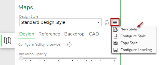
On the Maps pane > Design subtab, click Options, then click New Style.
-
Type a Name for your Design Style. This name is seen by both end users and administrators, so ensure it is clear and concise.
-
Click Create.
-
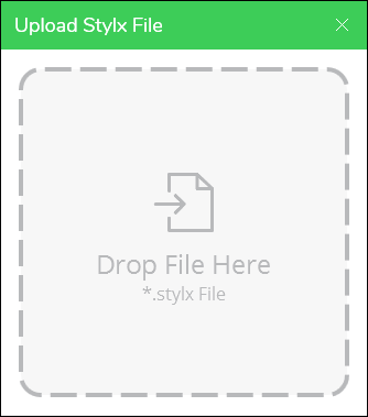
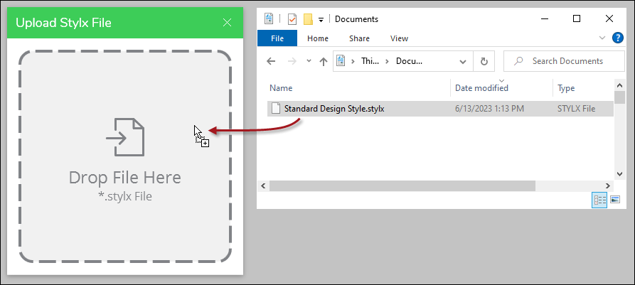
Notice an Upload Stylx File dialog appears. Leave it up for now, you will return in a moment.
-
Meanwhile, in ArcGIS Pro, ensure you have applied all your Style changes (clicking Apply is the same thing as saving a Style).
-
Navigate to where the .stylx file is saved. One easy way to do this is:
-
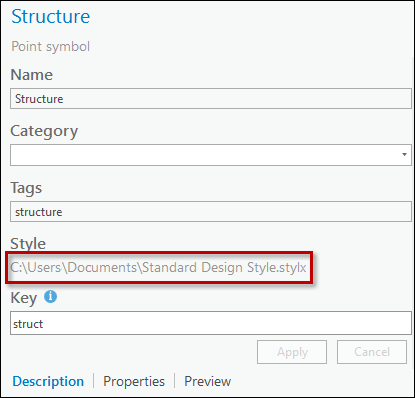
Click one of your symbols in the style.
-
On the Description pane, it shows the file path (your file path differs from the following image).
-
In Windows Explorer, go to that location.
-
-
Drag and drop your .stylx onto the Upload Stylx File dialog.
-
Notice your Style opens within the Design Style Configuration dialog.
-
Click Save. This saves a copy of the Design Style within the Designer XI file directories.
Now, you will navigate to where the .stylx is saved within the Designer XI file directories. Then, you will open that .stylx in ArcGIS Pro. In this manner, both applications are configuring the same Style.
-
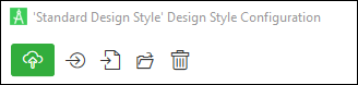
Click the Open Stylx File Location
 tool. Notice this brings you to the file location in Windows Explorer.
 -
Notice you see your .stylx files. They are named by their GUID. The number of files varies depending on how many Design Styles you have.
-
The Open Stylx File Location
tool does you a favor and highlights the .stylx you are working
on in Designer XI. If your .stylx file is not highlighted, sort by Date modified
to find your new file.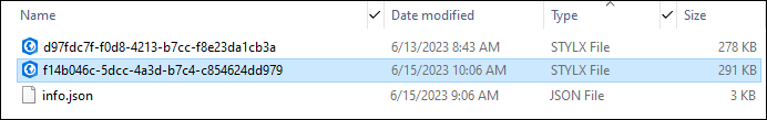
-
You are about to drag and drop your .stylx onto ArcGIS Pro, so take a moment to arrange the applications nearby.
-
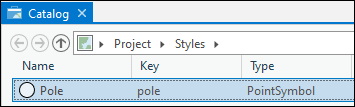
Drag and drop the highlighted .stylx onto ArcGIS Pro. You can drop it almost anywhere in ArcGIS Pro, but dropping it on the Catalog pane lets you see that it successfully landed in the Styles folder.
-
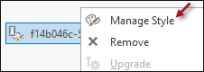
Right-click your Design Style, then choose Manage Style.
-
If you have two monitors, it is helpful to have Designer XI on one and ArcGIS Pro on the other.
With this environment setup, you are now ready to start matching the Keys between the two applications.
Match the Keys between Designer XI and ArcGIS Pro - Simple Symbols
With Designer XI and ArcGIS Pro open, you are ready to start matching Keys. In short:
-
Look up the .stylx Key in ArcGIS Pro for a component.
-
For the same component, either type that key in Designer XI or point to an attribute field that already has that key.
-
Repeat with all components.
To match the Keys, follow these steps (these steps use Poles as an example).
-
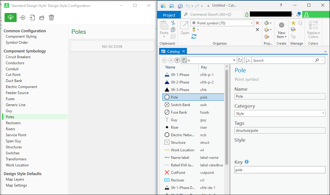
In ArcGIS Pro, locate the symbol for the desired component (in this case, it is Pole).
-
Take note of its Key (in this case, it is “pole”).
 NOTE: You can move the columns in ArcGIS Pro so that the Key column is directly after the Name column. This saves screen space and makes it easier to identify the appropriate Key.
 -
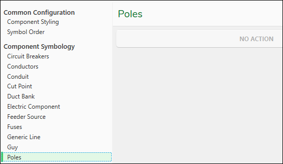
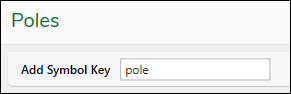
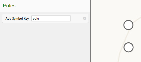
In the Designer XI Design Style Configuration dialog, locate the equivalent component (in this case, it is Poles).
-
Click No Action. If there is already one or more existing actions, you can add another. Hover your mouse beneath the Attribute row, then click when the green plus sign appears.
-
Now, you enter the same Key to match the .stylx file. There are two ways to do this: type the Key or point to an attribute field that already has the Key.
IMPORTANT: To be able to point to an attribute, you need to be able to see the component. This means you already have a default set of symbols as a starting point. If you do not have a starting set of symbols, type the Key personally.To type the Key:
-
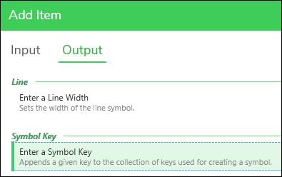
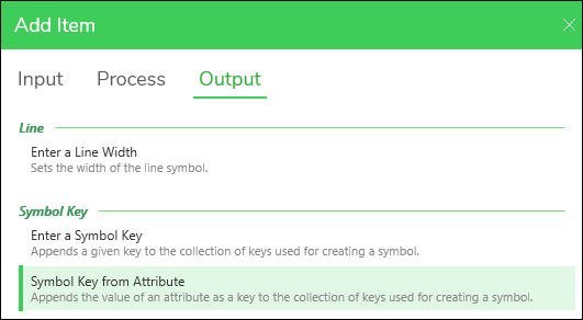
Click Output > Enter a Symbol Key. Then click Apply.
-
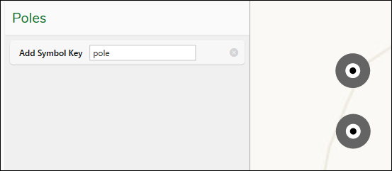
Type the Key. It must match exactly, including case.
-
Click the Apply Preview
 tool.
tool. -
If the Keys match, you should now see poles on the map in the symbol you set in ArcGIS Pro.
To point to an attribute field:
-
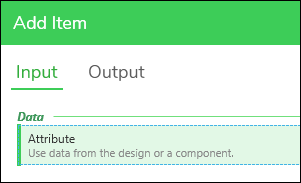
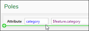
Click Input > Attribute. Then, click Apply.
-
Notice an Attribute row appears.
-
Click the Magnifying Glass
 tool.
tool. -
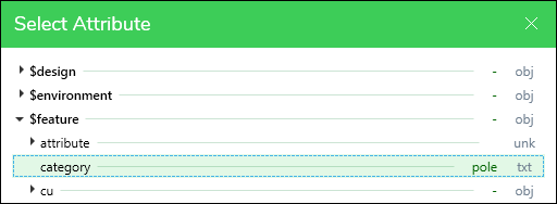
Click a representative component on the map (in this case, a pole).
-
Click the attribute field that contains the Key, then click Apply.
-
Hover your mouse beneath the Attribute row, then click when the green plus sign appears.
-
Click Output > Symbol Key from Attribute. Then, click Apply.
-
Click the Apply Preview
tool. -
If the Keys match, you should now see poles on the map in the symbol you set in ArcGIS Pro.
-
-
Repeat with other components.
This process establishes a simple Design Style. Keep reading subsequent topics to learn about more advanced symbology.
Modify Symbols
After matching the Keys, you might not like the way the symbol appears on the map. That’s OK. You can immediately modify it in ArcGIS Pro and see it change in Designer XI.
After matching the Keys, let’s assume you want to change the symbol. In this case, the administrator does not like the look of these poles.
-
In ArcGIS Pro, locate the symbol you want to change.
-
Work with its appearance using the various symbology settings in ArcGIS Pro.
-
When finished, click Apply.
-
Back in Designer XI, click the Apply Preview
tool. -
Notice the symbol updates to match ArcGIS Pro.
-
Repeat, as necessary.
Match the Keys between Designer XI and ArcGIS Pro - Enhanced Symbols
As stated in Add Key Modifiers for Enhanced Symbols, you can differentiate symbols for components. Perhaps you want to differentiate components by material, size, phasing, etc.
The process is the same as it was for simple symbols: match the Keys. It just takes a couple more layers of matching to satisfy the configuration.
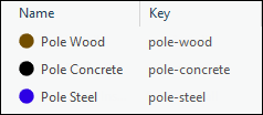
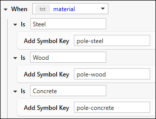
These steps use an example of three different kinds of poles: wood, concrete, and steel. Notice their symbols and their Keys in ArcGIS Pro.
To incorporate Key modifiers, follow these steps:
-
In ArcGIS Pro, take note of the Keys, including modifiers, for the component you want to symbolize.
-
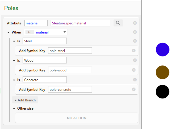
In the Design Style Configuration dialog, click the same component type (in this case, it is Poles).
-
Click No Action. If there is already one or more existing actions, you can add another. Hover your mouse beneath the Attribute row, then click when the green plus sign appears.
-
Click Input > Attribute. Then, click Apply.
-
Notice an Attribute row appears.
-
Click the Magnifying Glass
tool. -
Click a representative component on the map (in this case, a pole).
-
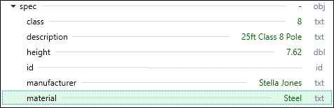
Click the attribute field that contains the attribute (in this case, material), then click Apply.
-
Hover your mouse beneath the Attribute row, then click when the green plus sign appears.
-
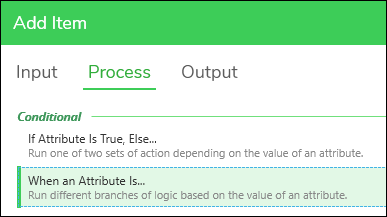
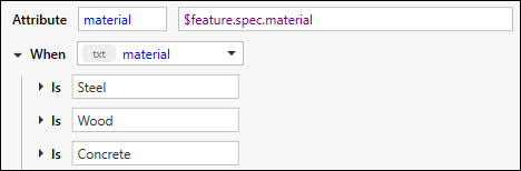
Click Process > When an Attribute Is. Then, click Apply.
-
Click Add Branch.
-
Click Add Branch again. Click OK if you receive a warning about a duplicate. That’s, OK. You are going to change it in a moment.
-
Click Add Branch one more time (and dismiss the duplicate message). You are giving yourself three rows because, in this case, there are three different material types.
-
Change the values accordingly. In this case, the values are Steel, Wood, and Concrete.
-
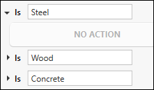
Click the arrow by the row to expand.
-
Click No Action.
-
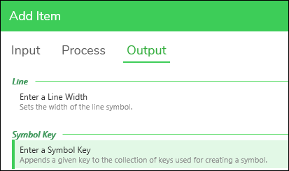
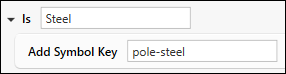
Click Output > Enter a Symbol Key. Then, click Apply.
-
Type the matching Key from ArcGIS Pro (in this case, it is pole-steel).
-
Repeat the process for the other values.
-
Click the Apply Preview
tool. -
If the Keys match, you should see your different symbols on the map.
Good to Know
There are other configuration choices in the Design Style Configuration dialog. The best approach is to download a sample from Designer XI Samples to see how these are used effectively. Some of the configurations include:
-
Enter a Line Width: For line components, you can change the line width conditionally based upon an attribute.
-
“Nested” When Statements: You are not limited to only one “When” statement. You can build multiple layers of statements to refine your symbols.
-
Overlays: You can incorporate two symbols into one component’s symbology, and overlay the symbols. For example, you can have a base symbol for a line feature, and then overlay another symbol on top to indicate removed or abandoned work functions.
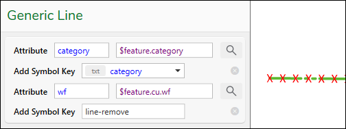 NOTE: In the image above, the symbol Key “line-remove” is a series of red Xs to indicate removal. You can use that same symbol on multiple line features. In other words, instead of creating a “pipe remove” symbol, a “conductor remove” symbol, a “conduit remove” symbol, etc., just create one line remove symbol and leave its name generic. Then, associate it to the Work Function for a line component (as seen in the image above), so that when a line is removed (regardless of what line type it is), the overlay appears. In short, you can use the same overlay for multiple components.
Match the Keys between Designer XI and ArcGIS Pro - Text Symbols
The process to match Keys for text symbols is essentially the same as for normal symbols.
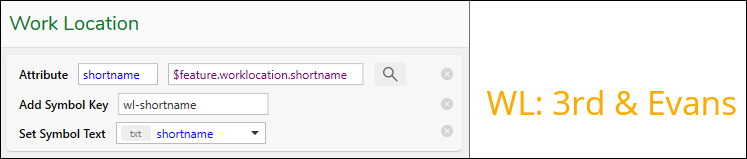
To match the Keys, follow these steps (these steps use Work Location Short Name as an example).
-
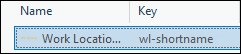
In ArcGIS Pro, locate the symbol for the desired component or feature (in this case, it is Work Location Short Name).
-
Take note of its Key (in this case, it is “wl-shortname”).
 NOTE: You can move the columns in ArcGIS Pro so that the Key column is directly after the Name column. This saves screen space and makes it easier to identify the appropriate Key.
 -
In the Designer XI Design Style Configuration dialog, locate the equivalent component or feature (in this case, it is Work Location).
-
Click No Action. If there is already one or more existing actions, you can add another. Hover your mouse beneath the Attribute row, then click when the green plus sign appears
-
Click Input > Attribute. Then, click Apply.
-
Click the Magnifying Glass
tool. -
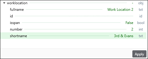
Click a representative component on the map (in this case, it is a Work Location).
-
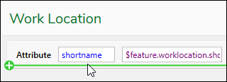
Click the attribute field that contains the text you want to use as the text symbol, then click Apply.
-
Hover your mouse beneath the Attribute row, then click when the green plus sign appears.
-
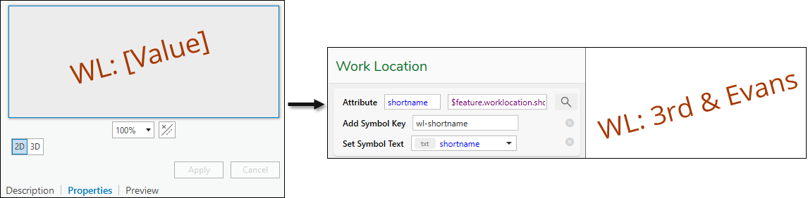
Click Output > Enter a Symbol Key. Then click Apply.
-
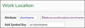
Type the Key. It must match exactly, including case.
-
Hover your mouse beneath the Symbol Key row, then click when the green plus sign appears.
-
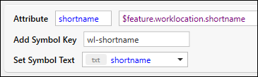
Click Output > Symbol Text from Attribute. Then click Apply.
-
Notice the Set Symbol Text is pointing to the Attribute you added earlier (in this case, shortname).
-
Click the Apply Preview
tool. -
If the Keys match, you should now see your text symbol that you set in ArcGIS Pro on the map.
-
If necessary, make changes to the text symbol in ArcGIS Pro, click Apply in ArcGIS Pro, then click the Apply Preview
tool. You can validate your changes in the map.