
Label Configuration within the Designer XI Application
Label configuration occurs within the Designer XI application. This allows you to continually preview how labels look as you configure them.
Prerequisites
The great benefit of configuring labels within the Designer XI application is you get real-time feedback on label appearance and position. Thus, it is strongly recommended to have a good “representative” design open while working with labels. The design must have representative components of each type you want to label. In other words, if you plan on creating a label for structures, then you need at least one structure visible in the map. If you plan on differentiating design components from existing features, then it is also helpful to have both visible in the map. This is because later in the steps below, you select the component type in order to see its attributes. If there is no component available to select, you can’t complete the label expression.
To configure labels directly within the Designer XI application, follow these steps:
-
As stated in the Prerequisites, open a representative design.
-
Ensure no components are selected.
-
In the Designer XI > Maps pane > Design subtab, click the Options
 icon, then click Configure Labeling.
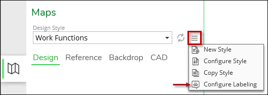 IMPORTANT: You need the Designer.Admin role to see this configuration tool.
 -
Notice the Label Configuration dialog opens.
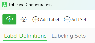
There are a few tools along the top of the dialog:
Icon
Tool
Description

Save
Save pushes label changes up to the Catalog hosted service. You can click Save as often as you require, and we recommend doing so periodically to back up your work.

Apply Preview
Click Apply Preview to see a real-time preview of your label configuration. You can click Apply Preview as often as you want. It is a great way to see how your labels look prior to saving them.

Add Label
This starts the process of creating a new label configuration.

Add Set
This creates a new Label Set to group labels.
A “set” is a collection of labels. For example, you might create a “Facility ID” label for many components. Then, you can group them together in a set so that you can turn them all on together and off together.
-
Click
. -
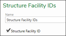
Type an intuitive name for the label. Other administrators see this name, so ensure it makes sense for your company. These steps use “Structure Facility ID” as an example.
-
Use the drop-down to choose the appropriate Component Type. Again, these steps use “Structures” as an example.

-
Click Create.
Now, you are going to create a Label Set. While it is not necessary to have a Set in order to complete your label, the Set is used to preview your label as you work.
-
Click
. -
Type an intuitive name for your Set. This name is seen by both administrators and end users, so ensure it is concise yet clear. These steps use “Structure Facility IDs.”
-
Click Create.
-
Click the Labeling Sets tab in the Labeling Configuration dialog and highlight the new Set in the list. Check the box next to the labels that should be included in the Set. The benefit of having multiple labels within a Set is that you can turn them all on together and off together. These steps check “Structure Facility ID,” which was the label created earlier.
-
Click the Save
icon.Now, you are going to turn on the Auto-Label Design Map
 tool. Again, while this is not necessary, it is going to allow
you to preview the label as you create it.
tool. Again, while this is not necessary, it is going to allow
you to preview the label as you create it. -
On the Maps pane, use the Labeling drop-down to choose your Label Set. In this case, it is “Structure Facility IDs.”
NOTE: The Label Configuration dialog is non-modal, so it does not lock the interface. This means you can click all the panes and tools while the dialog is open. -
Click the Auto-Label Design Map
tool to turn it on.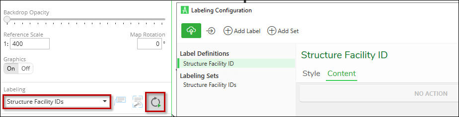
At this point, you won’t see any change on the map because you have not yet created the label expression. That part is next. -
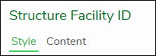
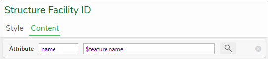
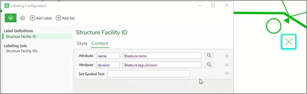
On the Labeling Configuration dialog, under Label Definitions click your label. For this example, that’s Structure Facility ID as seen in the image above.
-
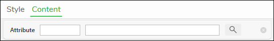
Notice there are two subtabs: Style and Content.
-
Click Content. This is where you choose which attributes to use for the label and, optionally, the conditions in which the component is labeled.
-
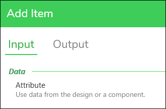
Click “No Action” to open the Add Item dialog.
-
For new Label Definitions, notice there are two subtabs on the Add Item dialog: Input and Output.
-
Click Input. This is where you choose the attribute fields to bring into the label expression.
-
Under Data, click Attribute to highlight, then click Apply.
-
Notice you have a new, empty Attribute row.
-
Click the Magnifying Glass
 icon to open the Select Attribute dialog.
 -
Notice it says, “Select a component in the map to view its attributes.” Using the Select
 tool, select the component type you are working with in the
map (in these steps, it is a structure). Alternatively, you can select
a component in the map before opening the Select Attribute dialog.
tool, select the component type you are working with in the
map (in these steps, it is a structure). Alternatively, you can select
a component in the map before opening the Select Attribute dialog. 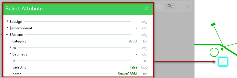 NOTE: The Label Configuration dialog allows you to select a different component type than selected in the map, but the Select Attribute dialog always syncs with the component selected in the map.
 -
Click the attribute you want to use as part of the label expression to highlight, then click Apply. For grouped attributes, be sure to expand the group and select an individual attribute. Notice Apply is not enabled if you highlight a group level attribute.
-
Notice your Attribute appears. In this case, the “name” was selected.
 NOTE: If you need to remove a row, click the “x” at the far right.
 -
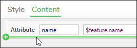
If you want to bring in another attribute, hover your mouse below the current attribute row. Notice a green plus sign appears.
-
Click when you see the green plus sign.
-
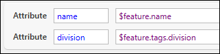
Repeat the steps above to bring in another attribute. These steps brought in a division tag attribute.
Now that you have your attributes selected, it is time to create the attribute expression.
-
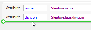
Now let’s add Output rules. Hover your mouse below the last attribute row, and click when you see the green plus sign.
-
In the Add Item dialog, click Output. After the first attribute expression is created, the Add Item dialog includes a third, Process, tab. This is covered in the next topic.
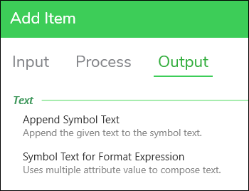
You can use Append Symbol Text to add simple static text to the symbol label.
-
Let’s explore creating an expression for Symbol Text. Click “Symbol Text for Format Expression,” then click Apply.
-
Notice a “Set Symbol Text” field appears in the Labeling Configuration dialog. This is where you type your label expression. When writing an expression, keep the following in mind:
-
Use the Attribute variable (the word in blue) within your expression.
NOTE: You can copy and paste the Attribute variable. -
Always surround the Attribute variable with curly brackets, for example, {name}.
-
You can add static text anywhere in the expression.
-
You can include line breaks by pressing Enter.
-
Click Apply Preview to get a sense of how the label appears (later in these steps, you work with label style).
In the animated demonstration, watch how the end user tries out various label expressions and notice the label preview change by the selected structure (click the demonstration to open it full-size in a separate browser tab).
-
-
Optionally, you can add a Format Specifier at the end of the variable to change the final look. After the variable, type a colon followed by the Format Specifier, which is a single letter. Case does matter. Here are some common examples of date and time values and how they transform the field (the “now” part is just an example; your variable depends on what attribute you are using):
-
{now:d} generates 7/7/2023
-
{now:g} generates 7/7/2023 9:38 AM
-
{now:m} generates July 7
-
{now:t} generates 9:38 AM
-
{now:y} generates July 2023
-
{now:D} generates Thursday, July 7, 2023
Review Microsoft’s help article Custom Format Strings, which includes format specifiers for numeric values as well as the complete list for date and time values.
Now that you have your attributes set, it is time to work on how the labels appear. See Style - Label Configuration topic for more information about all the choices surrounding the look and feel of labels.
-