
Electric - Utility Network
With each release and update, Designer XI supports more features within the electric Utility Network (UN). When a feature is supported, it is added to this list, along with its required fields.
When viewing these tables, keep the following in mind:
-
The fields displayed are the absolute minimum required for core Designer XI functionality. Having said that, your Designer XI implementation makes use of hundreds of additional fields across dozens of feature classes and object tables. These fields inform countless aspects and toolsets underlying the application’s functions. In short, your data model certainly has many more fields than these required fields
-
The Field Names displayed are the field names used within the ArcFM Configuration for the Utility Network (ArcFM UN). If you have used a different data model, then your field names might differ. That is OK. Read the Description column, which explains what the field is used for, then map that to the appropriate field in your company’s data model.
Electric UN Common Field Name Mapping
Applies to all Domain network and Structure network features and objects in the electric domain, except GenericLineComponent.
|
Designer Field Name |
Field Model Name (ArcFM UN Model) |
Required or Recommend |
Description |
|---|---|---|---|
|
AssetGroup |
ASSETGROUP |
Required |
Must belong to every feature class and object table that belongs to an electric domain network. |
|
AssetType |
ASSETTYPE |
Required |
Must belong to every feature class and object table that belongs to an electric domain network. |
|
Id |
GlobalID |
Required |
Designer XI is able to generate a Global ID for all design components. The Global ID does not change during the course of the design workflow. The Global ID is sent with the design during push, and it is used as a unique identifier. Further this ID could be beneficial for integrated systems, such as ADMS. This Designer XI Global ID field is mapped directly to the Esri GlobalID field in the schema. With the “supportsApplyEditsWithGlobalIds” property set to “true” on the feature service, Designer XI is allowed to write to this field. This means all applications can utilize a single GlobalID field throughout the component’s lifecycle. |
Electric Device Field Name Mapping
Applies to all devices in the electric domain including: BreakerBankWithTerminals, BreakerUnit, CapacitorBankWithTerminals, CapacitorUnit, Conductor, ConductorBank, ConnectivityNodeWithTerminals, DistributedGeneratorWithTerminals, ElectricNetworkComponentBankWithTerminals, FaultIndicatorBankWithTerminals, FuseBankWithTerminals, FuseUnit, LoadBreakBankWithTerminals, LoadBreakUnit, SectionalizerBankWithTerminals, SectionalizerUnit, ServicePointWithTerminals, SwitchBankWithTerminals, SwitchUnit, TransformerBankWithTerminals, TransformerUnit, VoltageRegulatorBankWithTerminals, VoltageRegulatorUnit.
|
Designer Field Name |
Field Model Name (ArcFM UN Model) |
Required or Recommend |
Description |
|---|---|---|---|
|
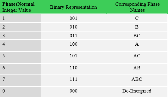
Phases |
PhasesNormal |
Required |
Identifies the named electrical phases (A, B, C) that are present and operational for each object in an electric domain network (both bank and unit). See Coded Domain Table below as example. |
|
OperatingVoltage |
VoltageGroup |
Required |
Represents multiple voltage values with a single encoded integer value for all feature classes and non-spatial objects in the electric domain network. Human readable information of nominal voltages associated with a piece of equipment. The text description should clearly and succinctly convey the nominal voltage details, e.g., Code = 7201, Description = 12.4/7.2 kV where L-L is 12.4 kV and L-G is 7.2 kV. |
|
LifeCycleStatusType |
LifeCycleStatus |
Recommend |
Domain coded value bound to a Network Attribute. Differentiates between facilities in different operational states, such as in-service, planned, abandoned, etc. Can be used to inform electric tracing behavior. This is mapped to the Esri field LifeCycleStatus, and it is only used for Import. |
|
WorkFunction |
LifeCycleStatus |
Recommend |
Tracks the design function of the component, for example, Install or Remove. Like LifeCycleStatusType field listed above, this field is also mapped to the Esri field LifeCycleStatus. But WorkFunction is only used for Push. |
|
FacilityID |
FacilityID |
Recommend |
Equipment identifier. |
|
InstallDate |
InstallDate |
Recommend |
|
|
Manufacturer |
Manufacturer |
Optional |
|
|
Model |
Model |
Optional |
|
|
SerialNumber |
Optional |
||
|
DesignID |
Optional |
Link to the ArcFM Designer Design Identifier. |
|
|
WMSCode |
Wmscode |
Optional |
Stores the code generated by the integrated WMS. Optional, but if populated it is used when doing a Remove and Replace action to automatically suggest a replace CU. |
Conductor Field Name Mapping
Applies to Designer Component Types: ConductorBank, Conductor.
|
DesignerField Name |
Field Model Name (ArcFM UN Model) |
Required or Recommend |
Description |
|---|---|---|---|
|
ConductorSize |
ConductorSize |
Required |
Domain lookup code for the nominal diameter of the conductive material. e.g., 1= “1/0”, 113 = “1000 KCM” |
|
ConductorMaterial |
ConductorMaterial |
Required |
Domain lookup code for the conductive material, e.g., 18 = “ACSR”, 23 = “AA”, 29=”Aluweld” |
|
IsNeutral |
Isneutral |
Recommend |
Domain lookup code to indicate whether this is a neutral conductor, e.g., 0=”No”, 1=”Yes” |
Switchable Device Field Name Mapping
For the unbalanced model, these field requirements apply to both Device feature classes and Junction object classes. For the balanced model, these field requirements only apply to Device feature classes.
Applies Designer Component Types: BreakerUnit, BreakerBankWithTerminals, FuseBankWithTerminals, CapacitorBankWithTerminals, DistributedGeneratorWithTerminals, FuseBankWithTerminals, FuseUnit, LoadBreakBankWithTerminals, LoadBreakUnit, SectionalizerBankWithTerminals, SectionalizerUnit, SwitchBankWithTerminals, TransformerBankWithTerminals.
|
Designer Field Name |
Field Model Name (ArcFM UN Model) |
Required or Recommend |
Description |
|---|---|---|---|
|
DeviceStatus |
DeviceStatus |
Required |
Open/closed state of the device for each bank and unit object (N/A for banks). In the unbalanced model, switchable bank devices should have a DeviceStatus that is closed unless all units contained by the bank are open, e.g., 0=”Open”, 1=”Closed”, 2=”Open, Traceable”. Open, Traceable allows for features to be owned by the subnetwork for things like export subnetwork but have no energized phase. |
|
Phases |
PhasesNormal |
Required |
In the unbalanced model, PhasesNormal for a bank device should be equal to the union of the PhasesNormal values of the units contained by the bank. |
|
EnergizedPhases |
phasesenergized |
Required |
In the unbalanced model, Energized Phases indicate which phases are conducting electricity, which could be a subset of the Normal Phases based on switching status throughout the network. |
|
RatedCurrent |
DeviceSize |
Recommend |
Current rating in amps. |
|
Breaking Current |
MaxInterruptingAmps |
Recommend |
Maximum current in amps that the device can safely interrupt. |
|
GangOperated |
GangOperated |
Required if device is gang operated |
Used to note in the unbalanced model if a switchable device is gang operated, e.g., 0=”No”, 1=”Yes”. |
Transformer Field Name Mapping
Applies to Designer Component Types: TransformerBankWithTerminals, TransformerUnit.
Transformer Unit Field Name Mapping
Applies to Designer Component Type: TransformerUnit.
|
Designer Field Name |
Field Model Name (ArcFM UN Model) |
Required or Recommend |
Description |
|---|---|---|---|
|
OperatingVoltage |
VoltageGroup |
Required |
Domain coded value. The voltage(s) going into the transformer’s primary winding. |
|
LowsideVoltage |
Secondarywindingconnection |
Required |
Describes the voltage(s) going into the transformer’s primary winding. |
|
HighsideVoltage |
primarywindingconnection |
Required |
Describes the voltage(s) going into the transformer’s secondary winding. |
Voltage Regulator Bank Field Name Mapping
Applies to Designer Component Type: VoltageRegulatorBankWithTerminals.
|
Designer Field Name |
Field Model Name (ArcFM UN Model) |
Required or Recommend |
Description |
|---|---|---|---|
|
Phases |
PhasesNormal |
Required |
Domain coded value. Value should reflect the combination of the phases that are covered by the contained voltage regulator units. |
|
RatedKVA |
devicesize |
Required |
Total kVA rating for the bank (adding up kVA ratings of the units), e.g., 25, 50, 300 |
|
OperatingVoltage |
VoltageGroup |
Required |
Domain coded value. Indicates the operating voltage at the In Bushing terminal of the Regulator, and should match the VoltageGroup code of each external feature (i.e., not counting the units) that is connected to the Primary terminal. |
Voltage Regulator Unit Field Name Mapping
Applies to Designer Component Type: VoltageRegulatorUnit.
|
Designer Field Name |
Field Model Name (ArcFM UN Model) |
Required or Recommend |
Description |
|---|---|---|---|
|
Phases |
PhasesNormal |
Required |
Domain coded value. Value should be a single phase, except when the unit represents a 3-phase voltage regulator. |
|
RatedKVA |
devicesize |
Required |
kVA rating for the unit (total kVA rating for the bank if this is a 3-phase voltage regulator unit). |
Capacitor Bank Field Name Mapping
Applies to Designer Component Type: CapacitorBankWithTerminals.
|
Designer Field Name |
Field Model Name (ArcFM UN Model) |
Required or Recommend |
Description |
|---|---|---|---|
|
Phases |
PhasesNormal |
Required |
Domain coded value. Value should represent the combination of the phases that are covered by the contained capacitor units. |
Capacitor Unit Field Name Mapping
Applies to Designer Component Type: CapacitorUnit.
|
Designer Field Name |
Field Model Name (ArcFM UN Model) |
Required or Recommend |
Description |
|---|---|---|---|
|
Phases |
PhasesNormal |
Required |
Domain coded value. Value should represent the combination of the phases that are covered by the contained capacitor units. |
|
Breaking Current |
KVar |
Required |
Domain coded value table that reflects Reactive Power. |