
Import Compatible Units
The process of creating CUs usually begins by defining CU Categories and CU Category Groups. While these are not strictly required, customers often find that CU Categories and CU Category Groups offer a convenient, logical way of keeping track of compatible units.
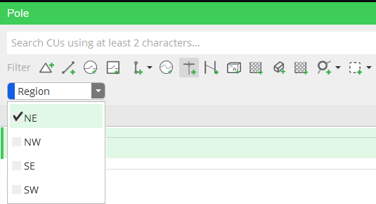
CU Categories are just collections of similar CUs—associating them with one another helps make them easier to find when searching in the Designer XI application. These are created in Solution Center > Designer plugin > Catalog Tab > CU Categories or in bulk using Excel. Create whatever category names and values that will benefit your end-users. Each CU Category must include at least one value as shown in the Region category example below.
CU Category Groups help identify which component types go with which CU Categories. This helps you allow or prevent the use of CU categories by group. Assigning a CU Category to a specific CU Category Group pre-filters any CUs later associated with the group. See Solution Center > Designer plugin > Catalog Tab > Create CU Category Groups. Each CU Category Group is identified as drawn or non-drawn and includes one or more Applicable Types and CU Categories. CU Categories might belong to more than one CU Category Group. For example, the CU Category Diameter would be useful for mains, valves, fittings, etc.
Now that you have your CU Categories and CU Category Groups defined (or decided not to use them), it’s time to create CUs and Macro CUs. While you can create these individually, we recommend using the Import/Export functions in Solution Center to create in bulk. Read the Solution Center topic on Workflow Resources to understand how to bulk create CUs, Macro CUs, and how to use Spec to CU mapping to assign equipment specs to each CU.
Remember, you should include your non-drawn CUs in the initial import. If the “Type” field for a non-drawn CU is not specified when specs are imported, it will default to “Unset.”
CUs can be created individually in Solution Center (see Compatible Unit topic), in bulk through Excel import, or by importing from your WMS. Your implementation team will help you determine the best way to create and connect your CUs to related equipment, CU categories, attributes, and available work functions.
A Macro CU is a combination of one driving (drawn) CU and one or more child (non-drawn) CUs. A macro CU may have one—and only one—driving CU, but there may be situations in which you want to combine more than one drawn CU into a commonly used or complex collection of assets. Applying Palettes and Templates, which can include multiple drawn CUs, is one option for handling these types of pre-sketched design components.
Keep in mind that any electrically networked feature is a bank and must be configured as a macro CU in order to be drawn in the Designer XI application. A list of Designer component types which require a macro CU, either GN and UN, is provided below.
|
Designer Component Type |
UN/GN |
|
BreakerBankWithTerminals |
UN |
|
CapacitorBankWithTerminals |
UN |
|
ElectricNetworkComponentBankWithTerminals |
UN |
|
FaultIndicatorBankWithTerminals |
UN |
|
FuseBankWithTerminals |
UN |
|
LoadBreakBankWithTerminals |
UN |
|
SectionalizerBankWithTerminals |
UN |
|
SwitchBankWithTerminals |
UN |
|
TransformerBankWithTerminals |
UN |
|
VoltageRegulatorBankWithTerminals |
UN |
|
ConductorBank |
GN, UN |
|
BreakerBank |
GN |
|
CapacitorBank |
GN |
|
ElectricNetworkComponantBank |
GN |
|
FaultIndicatorBank |
GN |
|
FuseBank |
GN |
|
LoadBreakBank |
GN |
|
SectionalizerBank |
GN |
|
SwitchBank |
GN |
|
TransformerBank |
GN |
|
VoltageRegulatorBank |
GN |
Remember, the process of creating a CU library is iterative. You and your implementation team will repeat this process until all CUs and their relationships are defined and working correctly throughout the end-to-end design process. Once the Designer XI application is live, do not delete CUs in Solution Center to avoid issues in designs.