
Design Tab
The Design tab comprises your most frequently-used tools, allowing you to quickly navigate the service area, select features on the map, place CUs, remove CUs, trace the network, mark up the map, and more.

By default, the tab is “locked” in a position where it is visible at all times. Double-click the tab to enable auto-hide, where the tab collapses while you interact with the map or other panes. To return to the locked position, double-click the tab again.
The tools on the Design tab share a few time-saving features:
-
Almost all of the tools “take over” your cursor. In other words, your cursor becomes the chosen tool. This is helpful when adding many of the same CUs to the design, as the CU persists with every click. To deactivate the chosen tool, click back on the Select tool.
-
With any tool activated, you can still navigate the map.
-
Click and drag to pan.
-
Use the mouse wheel to zoom in and out.
-
-
For CU placement tools, the first time you click the tool, the CU Search automatically appears. The chosen CU remains active until you search for a different CU. In other words, if your design uses the same pole CU ten times, you only need to search for it once, and the Place Pole tool uses the same CU for each subsequent placement. If you need to change the CU, simply search again.
|
Tool |
Use |
|
|---|---|---|
|
Select |
Click features to highlight them individually. Details about the selected feature appear in the Component Information pane. |
|
|
Select
by Rectangle |
Draw a rectangle around multiple items in the map to highlight them as a group. |
|
|
Place New
Transformer |
Click in the map to place a new transformer. |
|
|
Place New
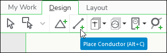
Conductor |
Click in the map to place a new conductor. Each click adds a vertex, and a double-click finishes the sketch. |
|
|
Place Structure |
Click this group to access structures such as conduit, poles, and surface structures. |
|
|
Place Conduit |
Click in the map to place a new section of conduit. Each click adds a vertex, and a double-click finishes the sketch. |
|
|
Place New Pole |
Click in the map to place a new pole. |
|
|
Place New Span Guy |
Click in the map to place a new span guy. Adding a span guy is a two-click process, and intermediary vertices are not allowed in the initial sketch. After sketching, you can right-click the span guy and choose Move. Then, you can add more vertices, if necessary. |
|
|
Place New Surface Structure |
Click in the map to place a new structure, such as a pad. |
|
|
Place New
Switchable |
Click this group to access switchable devices such as a fuse, recloser, and switch. |
|
|
Place New Fuse |
Click in the map to place a new fuse. |
|
|
Place New Recloser |
Click in the map to place a new recloser. |
|
|
Place New Switch |
Click in the map to place a new switch. |
|
|
Place New
Service Drop / Select CUs |
Click in the map to place a service drop (the first time you click, the tool prompts you for the Load Profile and conductor CU before sketching). |
|
|
Place Additional Equipment |
Click this group to access other electric assets such as capacitors, fault indicators, sectionalizers, and voltage regulators. |
|
|
Place New Capacitor |
Click in the map to place a new capacitor. |
|
|
Place New Fault Indicator |
Click in the map to place a new fault indicator. |
|
|
Place New Sectionalizer |
Click in the map to place a new sectionalizer. |
|
|
Place New Voltage Regulator |
Click in the map to place a new voltage regulator. |
|
|
Place Electric Network Component |
Click in the map to place a new network component. A network component is a generic feature against which many different kinds of CUs can be assigned. It allows you to place electric features not currently represented on the Design tab, such as arresters, capacitors, and regulators. |
|
|
Place New Work Location |
Click in the map to place a new Work Location, which is automatically numbered. |
|
|
Place Generic Line Component |
Click in the map to place a new generic line component. Each click adds a vertex, and a double-click finishes the sketch. A generic line component is a generic feature against which many different kinds of CUs can be assigned. It allows you to place line features that are not necessarily a part of your design, but can be helpful references for the crew. For example, you might want to sketch in nearby telecommunication lines for reference. |
|
|
Remove
Existing Components |
Click this tool and the cursor becomes a crosshair. Click and drag the cursor to “paint” over existing components that need to be removed as a part of your design. The application assigns appropriate remove CUs. |
|
|
Replace |
Click this tool to search for an install CU for a component type, then click the same component in the map. This places the install CU and simultaneously places the remove CU. It accomplishes a “same location” replacement. |
|
|
Trace |
Hover over components to see trace feedback in the map. To temporarily lock the trace results, click once. Trace results will remain visible even if you navigate the map. Clicking the map again re-activates the hover and trace function. Finally, clicking a different tool clears the trace results. |
|
|
Measure Tool |
Click in the map to perform linear measurements. |
|
|
Discover Tool |
Click to reveal previously-hidden components. Once revealed, click hidden components to make them visible again. Or, press and hold the Spacebar and hover over hidden components to reveal them en masse (this is called Brush Mode). |
|
|
Place Cut Point |
Click on an existing conductor (whether part of your design or part of the existing network) to place a cut point. A cut point breaks the line into two parts. If it is a drawn component that is part of your design, it breaks the CU into separate entries in the Project pane and re-calculates the length of the new segments. It does not de-energize the downstream portion of the line. |
|
|
Map Note |
Click in the map to place a text box. Text formatting options are provided within the same tool. Once placed, click the text box again to re-format, duplicate, or delete. Map Notes are visible both in the design and on the print. The look and feel of this tool is configurable at the company level, and your icon likely differs from this example image. |
|
|
Remove
Indicator |
Click in the map to place a point graphic, which is helpful to add emphasis to parts of the design. Once placed, use the Select tool to move or delete. Graphics are visible both in the design and on the print. The look and feel of this tool is configurable at the company level, and your icon likely differs from this example image. |
|
|
Line Indicator |
Click in the map to sketch a line graphic, which is helpful to add emphasis to parts of the design. Each click adds a vertex, and a double-click finishes the sketch. Once placed, use the Select tool to move or delete. Graphics are visible both in the design and on the print. The look and feel of this tool is configurable at the company level, and your icon likely differs from this example image. |
|
|
Dimension
Line |
Click in the map to sketch a line. The first click adds the begin vertex, and the second click adds the end vertex. Once placed, use the Select tool to reposition the vertices and change the length label. Dimension lines are visible both in the design and on the print. |
|
|
Area Indicator |
Click in the map to sketch a shape (polygon), which is helpful to add emphasis to parts of the design. Each click adds a vertex, and a double-click finishes the sketch. Once placed, use the Select tool to move or delete. Graphics are visible both in the design and on the map. The look and feel of this tool is configurable at the company level, and your icon likely differs from this example image. |
|
|
Address
Search |
Type address info you have (if possible, include city/state or ZIP code). The locator displays address matches. Click a result once to zoom to that location. This field also accepts latitude/longitude coordinates. Type the latitude (Y) first, followed by a comma, then type the longitude (X). |
|
|
Update
Catalog |
Click to get updated entries for CUs, groups, and equipment. |
|
|
Add Data |
Click to import additional feeders that were not originally included in the work order. This tool appears on the Design tab if your company uses Extended Feeder Manager (EFM). If your company does not use EFM, this tool is found on the Maps pane > Reference. |
|
|
Work Area Auto-Generation |
Click this tool to toggle the auto-generation functionality on or off. |
|
|
Work Area Auto-Generation is Running |
When toggled on, the application draws the Work Area for you in real time. The Work Area comprises buffers around all design components. The Work Area is drawn whether it is visible or hidden. |
|
|
Work Area Auto-Generation is Stopped |
When toggled off, the application stops drawing the Work Areas as buffers around all design components. Typically, this would be toward the end of the design when you need to make small adjustments to the Work Area. |
|
|
Work Area Visibility |
Click this tool to toggle the Work Area visibility on or off for your current design. This tool does not affect the visibility of other designers’ Work Areas, which are toggled on or off in the Maps Pane > Reference Maps (this ability to view other designers’ Work Areas is an optional configuration at your company). By default the Work Area is hidden. |
|
|
Work Area is Hidden |
When toggled off, the Work Area for your current design is not visible on the screen. This is the default. |
|
|
Work Area is Visible |
When toggled on, the Work Area for your current design is visible on the screen. |
|
|
Edit Work Area Tools |
Whether Work Areas are auto-generated or manually drawn, you can edit their shape using these tools. |
|
|
Add Work Area |
In the map, click to sketch new Work Area shapes. Each click adds a vertex of the shape. Double-click or press Enter to finish. |
|
|
Remove Work Area |
In the map, click to sketch a shape over an existing Work Area. The overlap between your sketch and the existing Work Area is removed, akin to a cookie cutter cutting out a section of the Work Area. Each click adds a vertex of the remove area. Double-click or press Enter to finish. |
|
|
Edit Work Area |
Click this tool to reveal the vertices and edges that compose the existing Work Area. Then, with the same tool, click and drag the vertices or edge midpoints into desired positions to modify the boundary of the Work Area. Double-click or press Enter to finish. With the same tool, you can also click and drag the entire Work Area into a new position. |
|


