Work Location Assignment Examples
Start Point Work Location Assignment Example
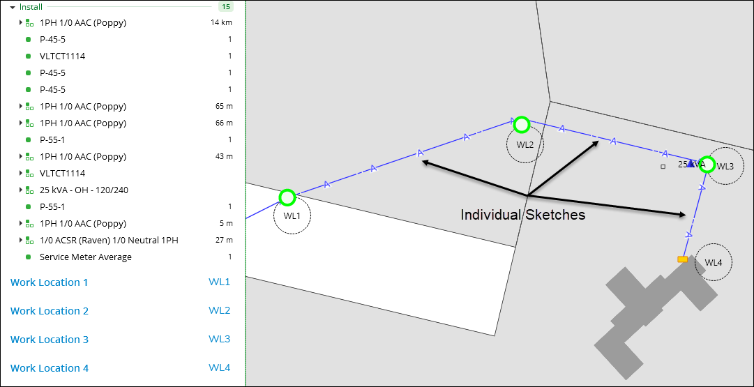
In the following image, the application uses the Start Point Work Location Assignment described above. Further, the linear component was sketched as individual lines among the structures. In other words, the user started and stopped the sketch for each span.
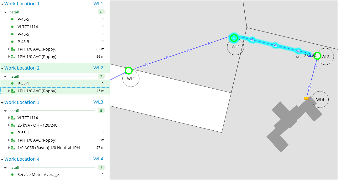
The Auto Assign Work Locations  tool assigns the linear components based upon their start points.
In the image below, notice how the “middle” linear component
has been assigned to Work Location 2. It was sketched west to east,
so its start point was closer to Work Location 2.
tool assigns the linear components based upon their start points.
In the image below, notice how the “middle” linear component
has been assigned to Work Location 2. It was sketched west to east,
so its start point was closer to Work Location 2.
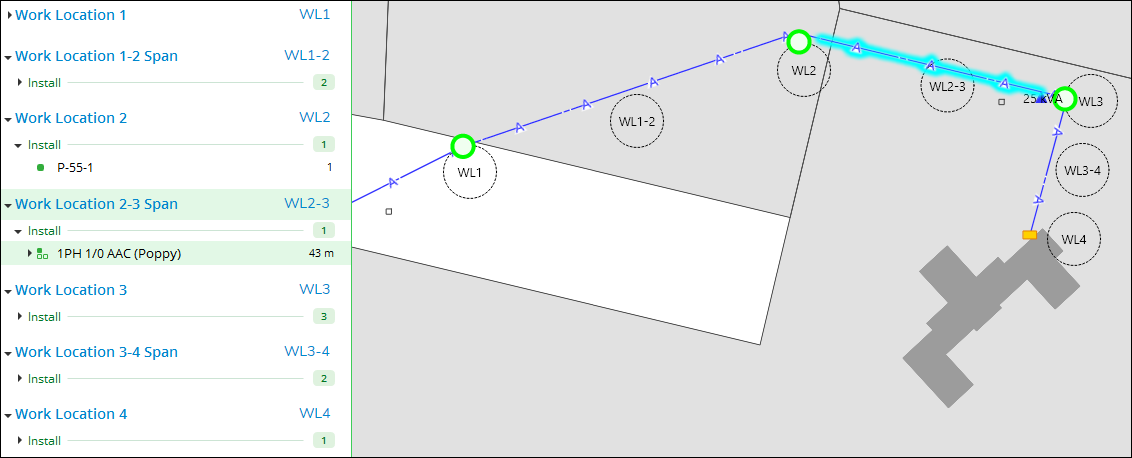
Start-to-End Work Location Assignment Example
Now, let’s look at the same design, but this time the application
is configured to use Start-to-End Work Location Assignment. The Auto
Assign Work Locations tool still assigns all the point components to their nearest
Work Locations, but for linear components it creates span Work Locations.
Notice how the same line from above (that used to be assigned to Work
Location 2) is now assigned to Work Location 2–3 Span.