
Adjust CAD
When you import a CAD file, it does not initially line up with the basemap. But, in Designer XI you can adjust the CAD file to match the basemap better. This is a similar process to adding control points in ArcMap via the Georeferencing toolbar.
In short, you click an identifiable location on the CAD (the “from point”), then click the same location on the basemap (the “to point”). For example, if both the CAD and basemap have building footprints, you could use a corner of the same building as a shared point. With at least two of these shared points, the application adjusts the CAD (moves it, stretches it, shrinks it, etc.) so that the shared points are coincident (or, in the same spot).
When using this tool, keep the following in mind:
-
You add these shared points in sets of two, and you can adjust the CAD as many times are you want.
-
Always click the CAD first, then the basemap.
-
You always adjust the CAD, and you cannot adjust the basemap.
-
You can Undo and Redo your adjustments.
-
If the CAD was drawn entirely out of proportion, there is only so much adjusting you can do within the application.
TIP: If you notice your most recent shared points are actually making the CAD more askew, then you’ve likely reached the limit of how much adjusting you can do.
To Adjust the CAD, follow these steps:
-
If necessary, Import the CAD.
-
You need to see the CAD and the basemap at the same time to perform the subsequent steps. So, if you need to move the CAD to your current map extent, click the CAD that you want to move to highlight it in green, then click the Move CAD File to Current Extent
 tool.
tool. -
If necessary, click the CAD that you want to adjust to highlight it in green. The one selected is the one you are going to adjust. Unselected CAD files are not adjusted.
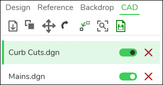 IMPORTANT: It is particularly important to always verify you are adjusting the correct CAD when you have multiple CAD layers in your design.
 -
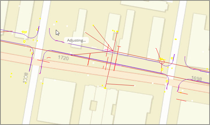
Click the Adjust CAD
 tool. Notice your cursor changes to say “Select ‘from
point’ on CAD file.”
tool. Notice your cursor changes to say “Select ‘from
point’ on CAD file.” -
Click the shared point on the CAD file.
-
Notice your cursor changes to say “Select ‘to point’ on the map.”
-
Click the shared point on the map.
-
Repeat the process with another shared point.
-
After two shared points, notice the application adjusts the CAD.
IMPORTANT: If your CAD has multiple layers within it, they are all adjusted together. -
Continue to add points to adjust the CAD further.
-
Save your work.
-
Click the Select
 tool or press Esc to disengage the Adjust CAD tool.