
Editing
These topics cover the various editing tools/capabilities available to you for editing.
Add Point CUs
- Search for your CU. There are a few ways to do this:
- Click the component type on the Design tab. If this is the first time you have clicked that component type, the CU Search automatically appears. Otherwise, it defaults to the previously chosen CU for that component.
- Right-click anywhere in the map and use the click wheel to choose your component type. If this is the first time you have clicked that component type, the CU Search automatically appears. Otherwise, it defaults to the previously chosen CU for that component.
- Press Ctrl+F. The CU Search appears.
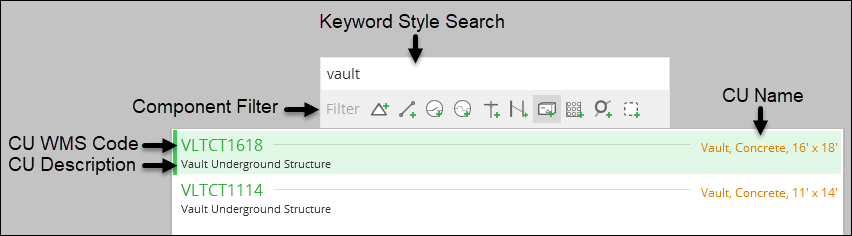
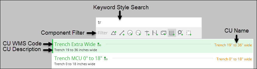
- In the CU Search dialog, type either part of the CU Name,
Description, or WMS Code. The field queries the CU catalog in a keyword
style. You can also use one of the component filters to reduce the
list of CUs.
- Double-click the CU.
- After you have chosen your CU, your cursor changes into
a crosshairs
 icon. Further, a tool tip displays your current
CU.
icon. Further, a tool tip displays your current
CU.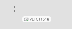 TIP: Need to change the CU? Press the middle mouse button, or press F. Both bring you back to the CU Search.
 - Click the map to place the CU.
- When placing an electric CU, the cursor provides feedback
regarding phase and snapping rules.
- The current CU is not compatible with the nearby conductor:

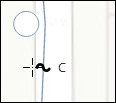
- The current CU is compatible, and in the following example, inherits
the C phase:
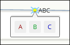
- The current CU is compatible, but it is a single phase CU snapped
to a multi-phase conductor. Choose the appropriate phase for the new
CU:
- The current CU is not compatible with the nearby conductor:
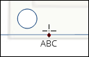
- When placing a non-electric point CU, you can snap to
a guide point for precision placement.
- When placing an electric CU, the cursor provides feedback
regarding phase and snapping rules.
- Your cursor persists as the add tool, allowing you to continue
to click and place additional CUs.
- To stop sketching, either click the Select tool or press Esc.
Add Line CUs
- Search for your CU. There are a few ways to do this:
- Click the component type on the Design tab. If this is the first time you have clicked that component type, the CU Search automatically appears. Otherwise, it defaults to the previously chosen CU for that component.
- Right-click anywhere in the map and use the click wheel to choose your component type. If this is the first time you have clicked that component type, the CU Search automatically appears. Otherwise, it defaults to the previously chosen CU for that component.
- Press Ctrl+F. The CU Search appears.
- In the CU Search dialog, type either part of the CU Name,
Description, or WMS Code. The field queries the CU catalog in a keyword
style. You can also use one of the component filters to reduce the
list of CUs.
- Double-click the CU.
- After you have chosen your CU, your cursor changes into
a crosshairs with snap point
 icon. Further, a tool tip displays your current CU.
 TIP: Need to change the CU? Press the middle mouse button, or press F. Both bring you back to the CU Search.
 - Hover near an existing feature, and for electric features,
the phases are displayed.
- Click to start sketching the CU.
- Each click adds a vertex to the line CU.
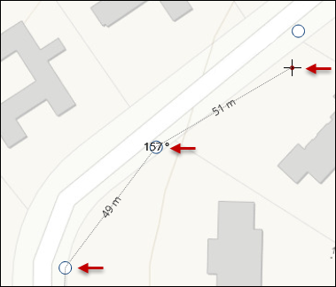
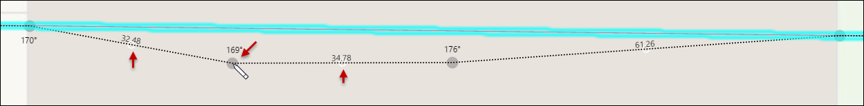
- When adding a line CU anchored to another line, the angle
between the new component and the existing line is shown. While sketching,
the total line distance as well as the segment distance are shown.
Holding Ctrl during placement will automatically snap to the closest
angle of 0, 30, 45, 60, 90, 120, 135, 150, or 180.

- If not starting from an existing line feature, the angle
will display after the 2nd vertex of the line has been placed. This
creates a reference line from which to calculate the angle. Again,
holding Ctrl will automatically snap to the closest angle of 0, 30,
45, 60, 90, 120, 135, or 180.

- To finish the sketch, either double-click your last vertex,
or if you have already sketched your last vertex, press Enter.TIP: If you press Esc during the sketch, it cancels the sketch.
- If prompted, for an electric CU, choose the appropriate phase.
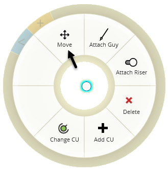
Move Install CUs and Work Locations
Using the click wheel, you can move any install CU or Work Location in your design. For a point feature, you can move it to a new location. For a line feature, you can re-sketch the shape of the line between the start and end points.
To move either an install CU or a Work Location:
- With the Select tool, right-click the CU (or Work Location)
and choose Move.
- For point features, the cursor changes to indicate the
move in progress. Click once more at the desired location.
 TIP: If moving a pole, risers and guys will move along too.
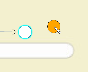
 - For line features, the cursor changes to indicate the
reshape in progress.
-
To move vertices, click and drag them into position. Click anywhere else on the map or press Enter to stop reshaping the line.
-
To move the entire line, click and hold the Move
 icon, then
drag into position. This disconnects the line from the network. Click
anywhere else on the map or press Enter to stop reshaping the line.
icon, then
drag into position. This disconnects the line from the network. Click
anywhere else on the map or press Enter to stop reshaping the line.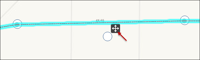
-
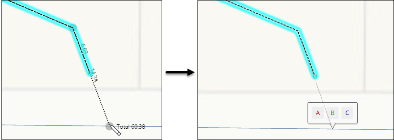
To snap into the network, move the endpoint of the conductor to snap into an existing conductor. Click anywhere else on the map or press Enter to stop reshaping the line.
-
When you snap into the network, the phase prompt appears for you to choose the appropriate phase.
 IMPORTANT: Depending on the original direction of the line sketch, the phase prompt might be off your screen. If so, press Esc to cancel the current snap. Then, zoom to an extent where you can see the entire line, then snap back into the network. Otherwise, you cannot see or use the phase prompt.
 -
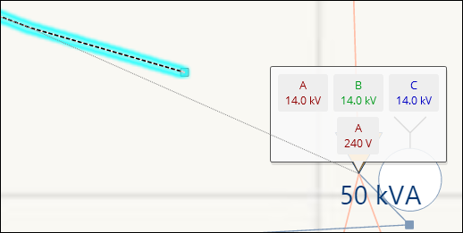
When you snap into a transformer, a prompt appears asking if you need to snap into the high side or low side of the component.
-
-
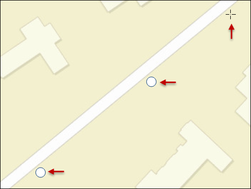
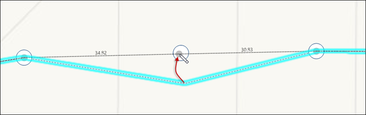
To add a vertex to an existing line, look for the mid-point vertex placeholders. In the following image, notice there are two mid-point placeholders:
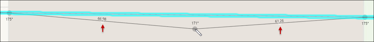 TIP: If you cannot see the placeholders, they are likely obscured by your current basemap. Change the basemap to a more contrasting color.
Click and drag the mid-point vertex placeholder into your desired position (the new vertex starts at the mid-point, but you can drag it anywhere). The placeholder becomes an actual vertex, and two new mid-point placeholders are displayed.
Continue to add new vertices in this manner, as needed.
-
- For point features, the cursor changes to indicate the
move in progress. Click once more at the desired location.
- For either a point or line feature, press Esc to cancel
the move.TIP: If you already moved or reshaped the CU, you can press Undo to return it to its original position or shape.
Delete CUs
There are a few ways to delete CUs you have sketched as a part of your design:
-
With the Select
 tool, select an individual
CU on the map, then press Delete.
tool, select an individual
CU on the map, then press Delete. -
With the Select by Rectangle
 tool, select a group of CUs on the map, then press Delete.
 -
With the Select tool, right-click an individual CU on the map. Then on the click wheel, choose Delete.

-
On the Project pane, select one or many CUs, then press Delete. Use the Shift and Ctrl keys to select multiple CUs.
Undo & Redo
You can undo and redo edits made on the Design tab. This includes placement or deletion of components, placement or deletion of map notes, and changes made to text inside a map note. You can also undo and redo changes you make while on the Layout tab.
Optionally, use Ctrl+Z to undo and Ctrl+Y to redo.