
Place Guide Point
The Place Guide Point tool  allows precise placement of a single or multiple guide points.
Click wheel functions help you to place points at an offset, at equidistant
spans from a starting point or based on an angle and distance from
the starting point. Guide points snap to existing poles and surface
structures, as well as to features in Reference Views and imported
CAD.
allows precise placement of a single or multiple guide points.
Click wheel functions help you to place points at an offset, at equidistant
spans from a starting point or based on an angle and distance from
the starting point. Guide points snap to existing poles and surface
structures, as well as to features in Reference Views and imported
CAD.
Use the Place Guide Point tool to create a new point anywhere in the design with a left mouse
click. Right-click on the selected point to open the click wheel or
enter the keyboard shortcut to select the desired mode for multi-point
additions. You can change or switch between modes by using the keyboard
shortcut at any time while actively placing guide points. The placement
modes are designed to work together.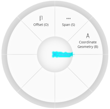
Guide points try to snap to existing points or line features, including those on Reference Views and imported CAD. Holding Ctrl while placing a guide point prevents snapping to all except another guide point. To prevent all snapping behavior, hold Ctrl+Spacebar.
Press Esc to exit the placement mode.
Offset Guide Points
The Offset mode will allow you to specify a distance from the starting or anchor guide point. Once a point is selected, right-click to open the click wheel or press O on the keyboard. You will see a Distance text box following the mouse cursor.
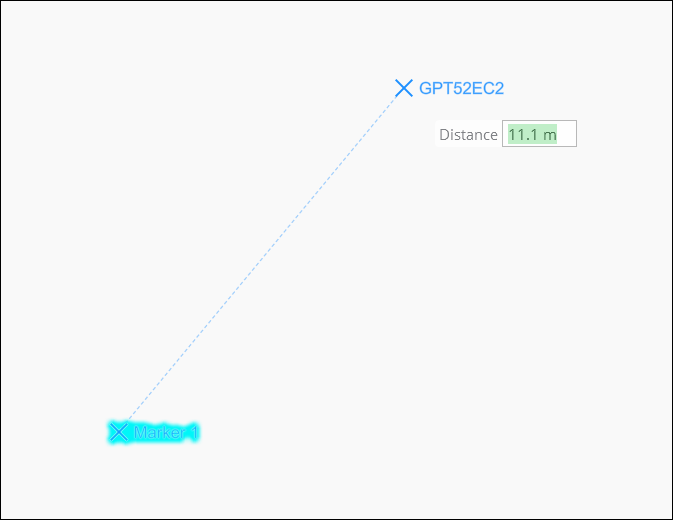
There are two methods to specify a distance when placing a new guide point:
-
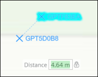
Right-click when the mouse cursor is at the desired offset distance and select the Lock Distance function on the click wheel. Or press H on the keyboard at any time to set a distance constraint. A lock symbol will appear next to the Distance text box.
-
Alternatively, you can specify a distance by entering a value with the keyboard. Any keyboard entry will appear in the Distance text box while it is displayed. Press Enter to update the offset and lock the distance constraint. If units are not entered with the distance value, the units of the previous point will be assumed.
Right-click in the map and select the Unlock Distance function from the click wheel or press H on the keyboard to remove the distance constraint. The distance lock can also be removed by clearing the distance value using Backspace or Delete on the keyboard.
While in Offset mode, you may continue to add new guide points by mouse click. The distance constraint will persist with each additional point until removed by unlocking. Exit Offset mode by pressing Esc or selecting another function from the click wheel or using a keyboard shortcut.
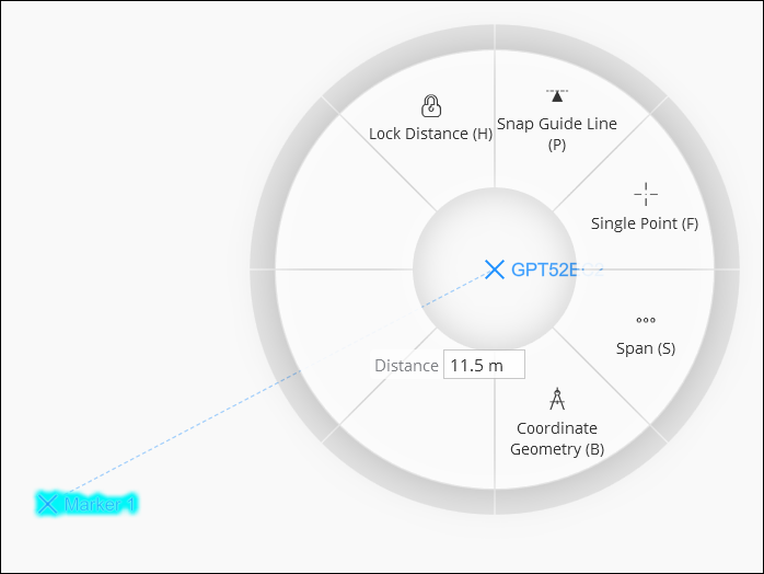
Switch to Single Point (F), Span (S), or Coordinate Geometry (B) placement mode at any time by pressing the keyboard shortcut or right-clicking themouse to open the click wheel. You can combine or alternate between placement modes at any time.
Use the Snap Guide Line (P) function to create a reference line for additional points. This function is available in Offset or Span mode.
Span Guide Points
Span mode allows placement of multiple guide points at equidistant spans from a starting point. This can be helpful in determining a midpoint between two points, finding placement points for pole runs, or determining how to bisect a line given a maximum offset.
Once a point is selected or placed, right-click to open the click wheel or press S on the keyboard. You will see Span and Max distance text boxes following the mouse cursor. Span distance is the length of each divided segment from the starting point to the current mouse position. Max distance is the maximum offset allowed between segments before that segment will be divided.
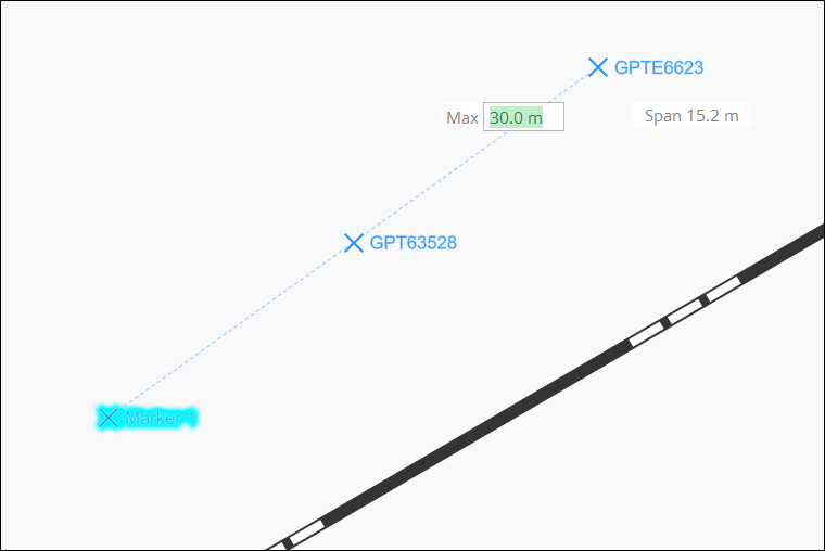
Max distance can be updated by keyboard entry with no need to click in the field. Any keyboard entry will appear in the Max text box while it is displayed. Press Enter to update the distance and display the span point preview. If no unit is included, the unit of the previous point will be assumed.
Moving the mouse around will provide a preview of the segment points and allow additional points to be added. Clicking the left mouse button will place all the points in a single transaction and allow additional point spans to be created.
Span mode can be cancelled by pressing Esc or right-clicking and selecting a different function from the click wheel.
Angle Information for Offset and Span
The addition of angles to guide point placement works like the angle feedback provided when placing linear CUs.
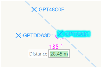
While using the Place Guide Points tool to place a point, select the Offset (0) or Span (S) mode from the click wheel or by pressing the keyboard shortcut. As you place a third point, the angle will display. This relative angle may be constrained to 0°, 30°, 45°, 60°, or 90° (and equivalent mirrored angles beyond 90°) by holding Ctrl.
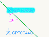
If the starting point is on a line feature, the angle will display with the placement of a second point. Holding Ctrl will snap the angle to one of the constrained choices if desired.
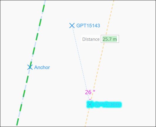
You may also create a reference line parallel to an existing line feature. The angle of the first point will be displayed.
To create the reference line, place a point on the map and select Offset (O) or Span (S) mode from the click wheel or keyboard shortcut. Next, select Snap Guide Line (P) on the click wheel or press P on the keyboard to add a reference line parallel to an existing line feature. A cursor hint will direct you to select a point on the existing line. The angle will display as you place points in relation to the orange reference line. Again, holding Ctrl will snap the angle to one of the constrained choices.
Coordinate Geometry
Coordinate Geometry provides a way to place a guide point offset from another point by entering a bearing or azimuth angle and a distance.
Click the Coordinate Geometry function or press B on the keyboard to open the Coordinate Geometry dialog while using the Place Guide Point tool. Notice the map pans to center on the selected point.
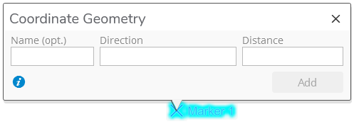
The Name field is optional. If entered, the new Guide Point will be given this name. If no name is entered, the application will generate a name for the point. The point can be renamed later if desired.
The Direction field can take a bearing or an azimuth angle. A bearing describes the angle rotated from the north or south geodetic toward the east or west direction.
Bearing angles may be entered in the following formats:
-
N45° 30' 15"E
-
N45 30 15E
-
N45-30-15E
-
45-30-15-1 (quadrant 1=NE 2=SE 3=SW 4=NW)
Alternatively, Direction can be given as an azimuth angle which is the degrees from true north, rotated in a clockwise direction.
Azimuth angles may be entered in the following formats:
-
45.5°
-
45.5
The Distance can be entered as a length such as:
-
200m
-
200ft
-
200’
-
200
You may use Enter to cycle through the fields and the Add button on the dialog. If the required Direction and Distance field entries are valid, the Add button will be enabled. Pressing Enter while the Add button is enabled and in focus will add the point and pan the map to the new location. Add as many points as desired while the dialog is open. Each new point will be relative to the previous point added. Press X to close the dialog. Undo and Redo work as expected with this feature.