
Rotate
After you sketch a point component, you can then rotate it into a desired position.
To rotate a point component, follow these steps:
- On the Design tab, click the Select
 tool.
tool. - Right-click the component and choose Rotate.
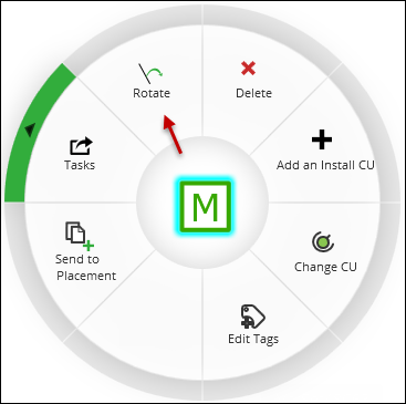
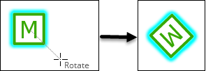
- Move your cursor into the desired, rotated position, then
click. You are choosing which direction the “top” of
the symbol should point. Notice in the image, the letter “M”
is now pointing down and to the right because the Rotate line was
down and to the right.
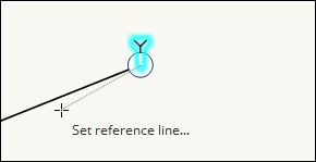
 TIP: Need a reference line to set the proper rotation? For example, sometimes an anchor guy is angled in relation to an incoming conductor.
-
When you see the rotate line, press R once on your keyboard. This changes the rotate line to a reference line. Each time you press R, it toggles between the rotate and reference lines.
-
Once in a desired position, click once to set the reference line.
-
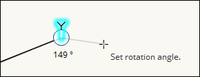
Once the reference line is set, move your cursor. Notice, the angle of deflection is displayed in real time.
-
Once the desired angle is displayed, click once to rotate the anchor guy to that angle.
IMPORTANT:The angle produced from the reference line is not the final angle of record. In other words, it is not the angle that is pushed back into the GIS. For the GIS angle, your company configures the application to either use Arithmetic or Geographic (this setting is found in Solution Center > Designer > Mapping > Electric/Gas Options):
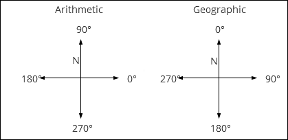
In other words, if your anchor guy is pointing due east, no matter how you got it to point due east, its final angle of rotation would be 0 degrees if using Arithmetic or 90 degrees if using Geographic.
-