
Import CAD File
If you have a CAD file to use as a reference for your design, you can import it directly into Designer XI.
To import a CAD file, follow these steps:
-
In the Maps pane > CAD, click the Import CAD File
 tool.
tool. -
Browse to the CAD file and Open it.
-
The application supports the CAD file types of:
-
Drawing Exchange Format (.dxf)
-
AutoCAD file (.dwg)
-
MicroStation file (.dgn)
-
-
-
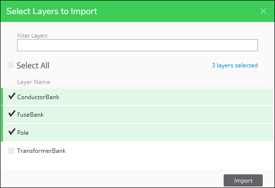
Use the Select Layers to Import dialog to choose the appropriate CAD layers.
-
Use the Filter Layers field to type part of the layer name.
-
This filter acts as a keyword filter, searching any part of the name.
-
It returns all matching results.
-
-
Check the layers you want to import. Notice it keeps track of the number of layers selected.
TIP: The Select All box respects your filter. In other words, if you started with 60 layers and filtered down to 10, Select All checks the 10 layers, not all 60.
-
-
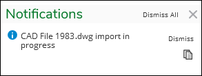
Click Import. Notice you receive a Notification of the import in progress. You also receive a notification when it is complete.
 IMPORTANT:
-
You might receive a “Length Unit Mismatch” notification:
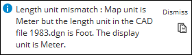
This message can be broken down into, “Map unit is (A) but the length unit in the CAD file is (B). The display unit is (C).” These units are:
-
A: The unit associated with the design layer’s spatial reference (in other words, the unit your design components follow, typically feet or meters).
-
B: The unit saved within the CAD file (again, typically feet or meters).
-
C: The default linear unit set company wide for all Designer XI designs (this is set in Solution Center).
The notification displays when A does not equal B. In the example above, the Map unit is in meters, but the CAD was saved in feet.
The good news is you can still use the CAD and use all the tools described in the subsequent topics. But to avoid this notification, it is ideal if your company used the same length unit across applications.
-
-
-
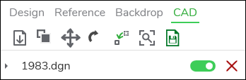
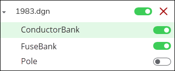
When finished, notice the CAD file appears in the Maps pane > CAD.
-
You can toggle the entire CAD layer on and off.
-
You can remove the layer, if needed.
-
You can click the expand arrow to see the individual layers within the CAD. At that point, you can toggle their visibility individually. Further, you can use Ctrl and Shift to highlight multiple layers, then toggle them on or off as a group.
-
-
If the CAD is not visible in the map, you would most likely use the Move CAD File to Current Extent
 tool and the Adjust CAD
  tool to perform georeferencing directly in Designer XI.IMPORTANT: Have you already georeferenced the CAD and still can’t see anything? First, ensure the CAD layer is toggled on. Then, try a different basemap. Perhaps the color of the CAD is blending into the background.
When importing a CAD file, keep the following in mind:
-
If the CAD file has the same spatial reference as the one used by default by Designer XI, the CAD is positioned where it was saved in the CAD application.
-
If the CAD file and your application do not have the same spatial reference, that is OK. Continue reading the topics in this help chapter such as Move CAD File to Current Extent and Adjust CAD to learn how to reorient the CAD file to match your design area.
-
Designer XI uses the CAD file name for its display name. You cannot change the display name once it is imported.